Disk apparatus and electronic apparatus including same

Inactive Publication Date: 2006-05-25
ORION ELECTRIC CO LTD
View PDF7 Cites 0 Cited by
  • Summary
  • Abstract
  • Description
  • Claims
  • Application Information

AI Technical Summary

Benefits of technology

[0006] The present invention has been achieved to solve the conventional disadvantages. It is an object of the present invention to provide a disk apparatus capable of preventing misinsertion of a disk, and easily and visually recognizing insertion of the disk in the disk apparatus, and an electronic apparatus including the disk apparatus.
[0008] With the constitution of the first aspect of the present invention, in the disk reproducing state in which a disk is inserted in the main body frame, the opening is inclined so as not to erroneously insert a different new disk into the main body frame through the opening. It is, therefore, possible to prevent misinsertion of the disk into the main body frame. In addition, the opening member assembled in the front surface of the disk apparatus is inclined in the disk reproducing state in which the disk is inserted in the main body frame. A user or the like can, therefore, visually recognize this inclined opening member and easily confirm whether or not the disk is inserted in the main body frame.
[0010] With the constitution of the second aspect of the present invention, the disk apparatus that reproduces information from the disk is included in the electronic apparatus, e.g., a television receiver, including a display unit. By including the disk apparatus in the normally popular electronic apparatus such as the television receiver, the practicability of the electronic apparatus is enhanced.
[0011] The disk apparatus according to the first aspect of the present invention includes: a main body frame into which a disk is inserted; an opening member in which an opening for inserting the disk into the main body frame is formed; and a rack loading member moved forward or backward within the main body frame, wherein a convex portion formed on the opening member is inserted in a guide groove formed in the rack loading member, the opening member is rotatably and pivotally supported by the main body frame, in a disk reproducing state in which the disk is inserted in the main body frame, the rack loading member is moved backward, the convex portion inserted in the guide groove is slidably moved along the guide groove to follow a backward movement of the rack loading member, and the opening member rotated and inclined to follow a slidable movement of the convex portion is assembled in a front surface of the disk apparatus. In addition, it is possible to prevent the disk from being damaged by misinsertion of a different disk, to visually recognize that the opening member is inclined, and to easily confirm that a disk is inserted in the main body frame at a glance.
[0012] The electronic apparatus including the disk apparatus according to the second aspect of the present invention includes, in the disk apparatus of the first aspect, a display unit that displays an image based on output data output when information is reproduced from the disk. Thus, by including the disk apparatus in the normally popular electronic apparatus such as the television receiver and a computer monitor, an electronic apparatus with an excellent practicability can be provided.

Problems solved by technology

Due to this, once the disk is arranged at a predetermined position within the disk apparatus, a user cannot confirm afterwards, for example, whether or not the disk is inserted unless the user operates an eject button or the like for discharging the disk.
The operation is quite cumbersome.
For this reason, when a disk is already arranged within the apparatus, if a different new disk is to be inserted into the disk apparatus, the different new disk may possibly contact with a member within the disk apparatus or with the previously inserted disk to thereby damage a surface of the disk.

Method used


Image

  • Disk apparatus and electronic apparatus including same
  • Disk apparatus and electronic apparatus including same
  • Disk apparatus and electronic apparatus including same

Examples


Embodiment Construction

[0020] A most preferred embodiment of the present invention will be described hereinafter with reference to FIGS. 1 to 7A and 7B.

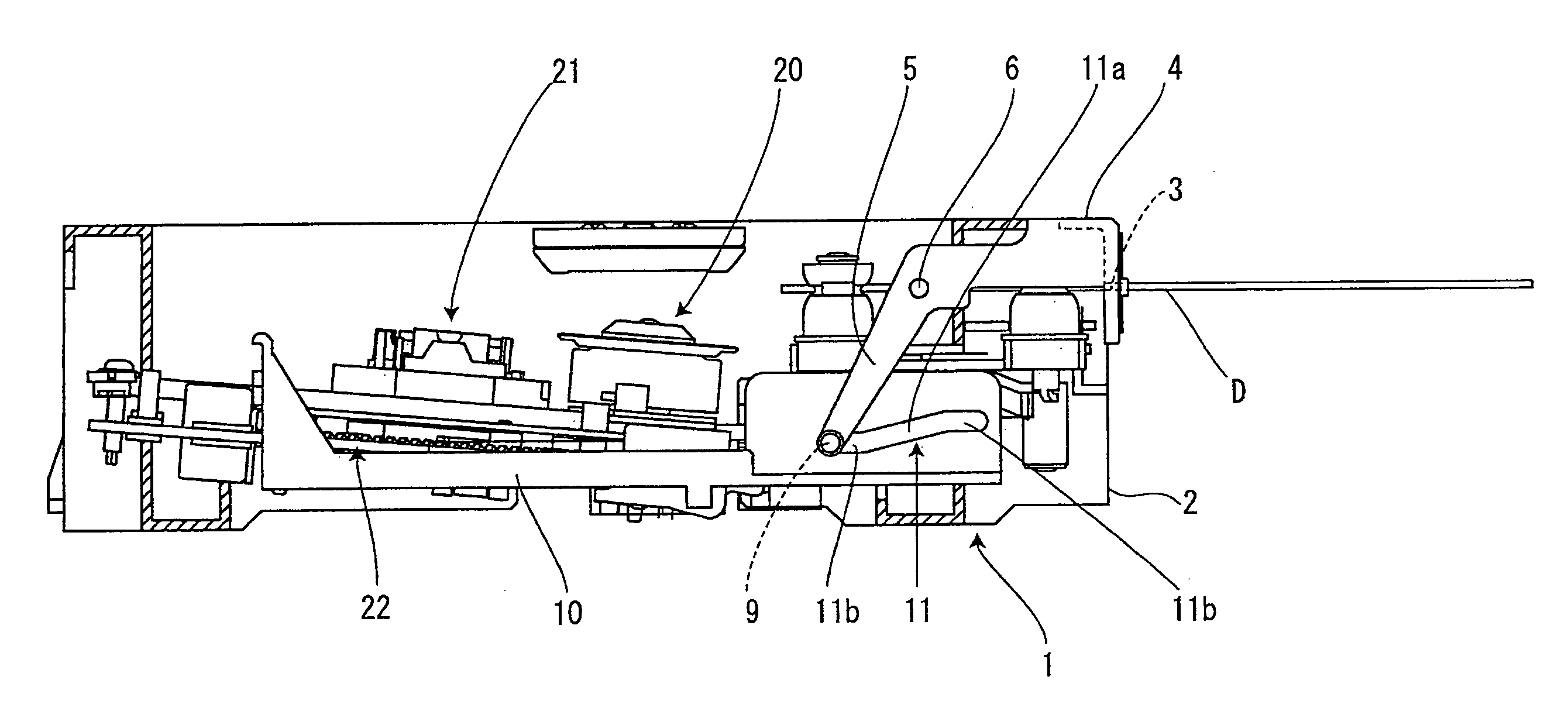
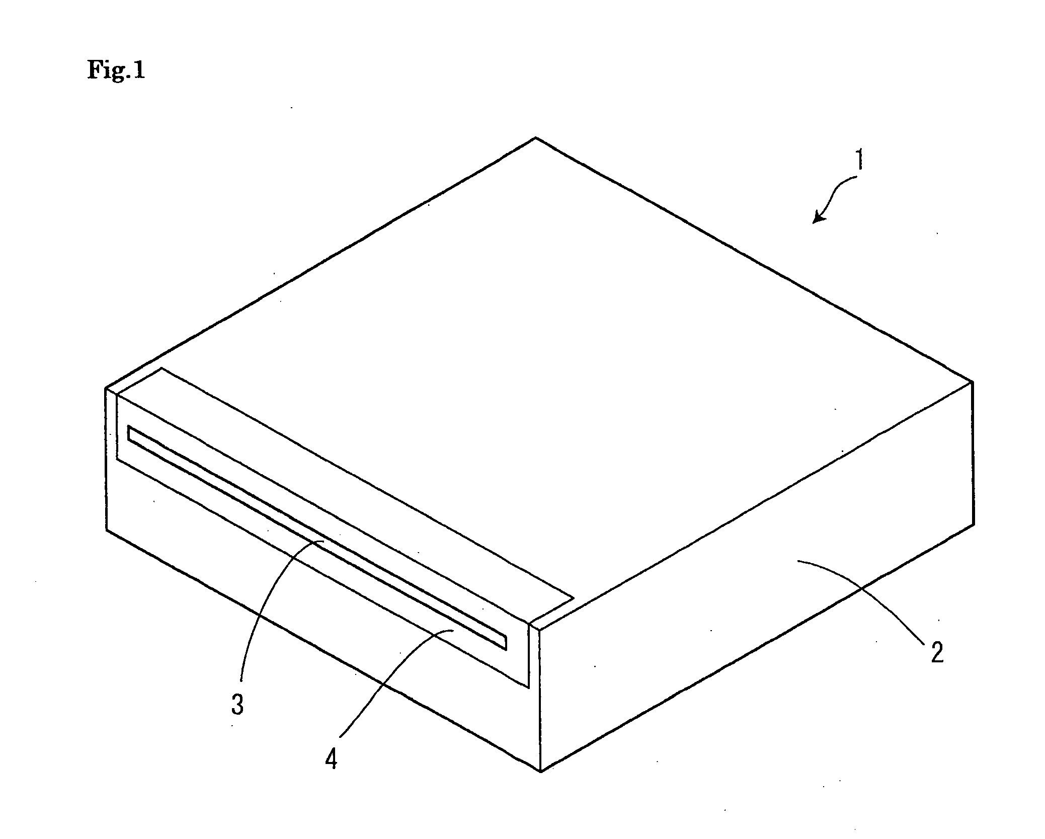
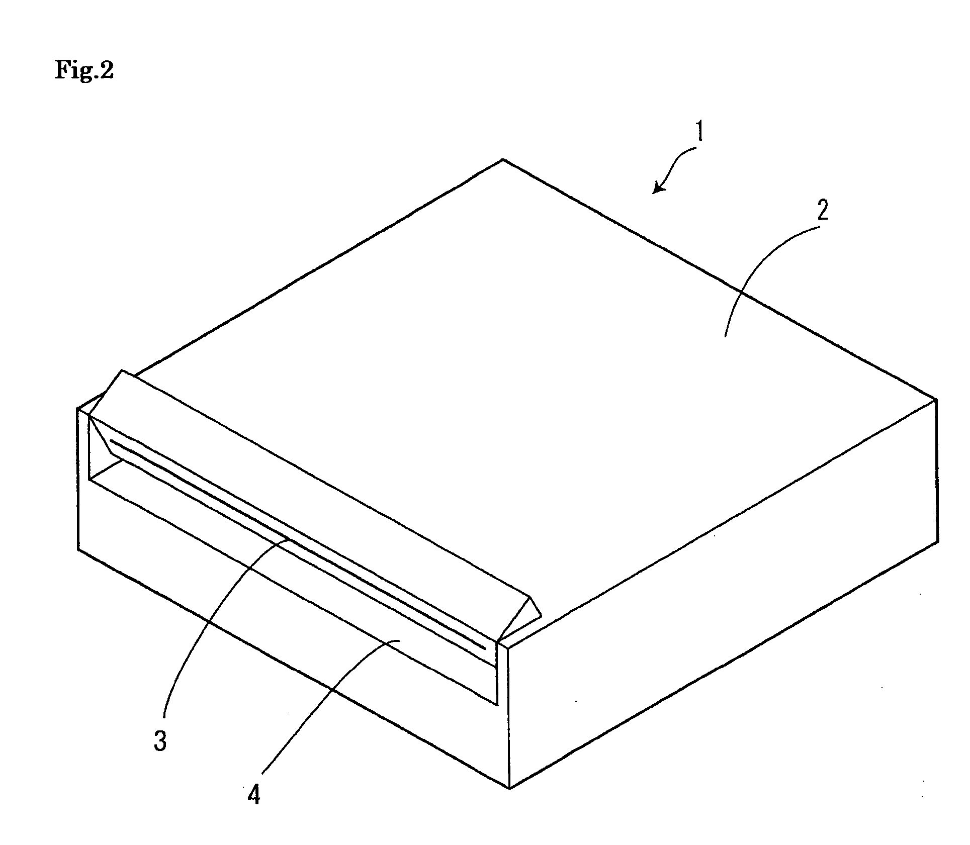
[0021]FIG. 1 is a perspective view of a disk apparatus according to one embodiment of the present invention. FIG. 2 is a perspective view that depicts a state in which a disk has been inserted in the disk apparatus. FIG. 3 is a cross-sectional view that depicts a schematic configuration of the disk apparatus. FIG. 4 is a front view of the disk apparatus according to the embodiment. FIG. 5 is a schematic cross-sectional view that depicts a state in which the disk is to be inserted into the disk apparatus. FIG. 6 is a schematic cross-sectional view that depicts a state in which the disk is inserted in the disk apparatus, and in which an opening member is inclined. FIGS. 7A and 7B are explanatory views that show operations when the disk is inserted into the disk apparatus.

[0022] An entire form of a disk apparatus 1 is constituted by a generally box-shaped m...


PUM


Abstract

A main body frame 2 is provided with an opening member 4 in which an opening 3 is formed, the opening being inclined during a disk D reproducing state in which the disk D is inserted in the main body frame 2 to prevent so as not to erroneously insert a different new disk into the main body frame 2. It is thereby possible to prevent misinsertion of the different new disk into the main body frame 2, visually recognize the inclined opening member 4, and easily confirm whether or not the disk D is inserted in the main body frame 2.

Description

BACKGROUND OF THE INVENTION [0001] 1. Field of the Invention [0002] The present invention relates to a disk apparatus that can directly insert or discharge a disk into or from an interior of the apparatus and an electronic apparatus that includes the disk apparatus. More specifically, the present invention relates to a disk apparatus that can prevent misinsertion of a different new disk into an interior of the apparatus while a disk is already inserted in the interior thereof and an electronic apparatus that includes the disk apparatus. [0003] 2. Description of the Related Art [0004] Conventionally, an electronic apparatus, e.g., a television receiver, including therein a disk apparatus into an interior of which a flat disk such as a CD-R is inserted and which can record and reproduce data such as voice data or video data has been employed. In recent years, in view of reducing the number of components, a so-called slot-in type disk apparatus into which a disk is directly inserted di...

Claims


Application Information

Patent Timeline
IPC IPC(8): G11B17/04
CPCG11B17/0405G11B17/051
Inventor WATANABE, KAZUHIRO
Owner ORION ELECTRIC CO LTD
Why Eureka
Try Eureka