Detachable light-emitting device

Inactive Publication Date: 2007-02-06
THERMO CLINICAL LABSYST
View PDF7 Cites 5 Cited by
  • Summary
  • Abstract
  • Description
  • Claims
  • Application Information

AI Technical Summary

Benefits of technology

[0013]The light-emitting device of the present invention can be easily attached to and detached from an object, thereby adding light emitting effect and function to the object.
[0014]The main objective of the invention is to enable a light-emitting device to be ea

Problems solved by technology

However, as such a light-emitting device fits only to one of the afore-ment

Method used


Image

  • Detachable light-emitting device
  • Detachable light-emitting device
  • Detachable light-emitting device

Examples


Embodiment Construction

[0028]Further aspects, objects, desirable features, and advantages of the invention will be better understood from the detailed description and drawings that follow in which various embodiments of the disclosed invention are illustrated by way of example. It is to be expressly understood, however, that the drawings are for the purpose of illustration only and are not intended as a definition of the limits of the invention.

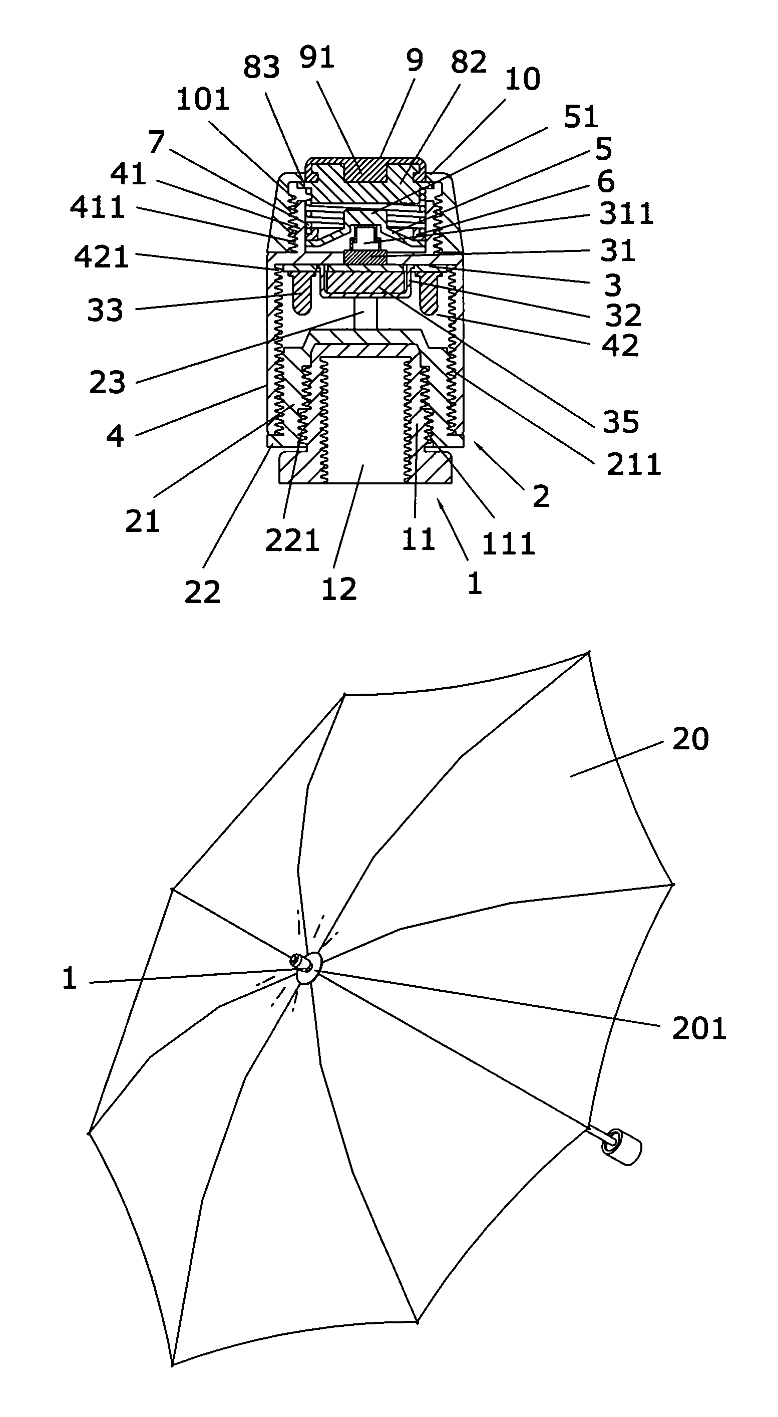
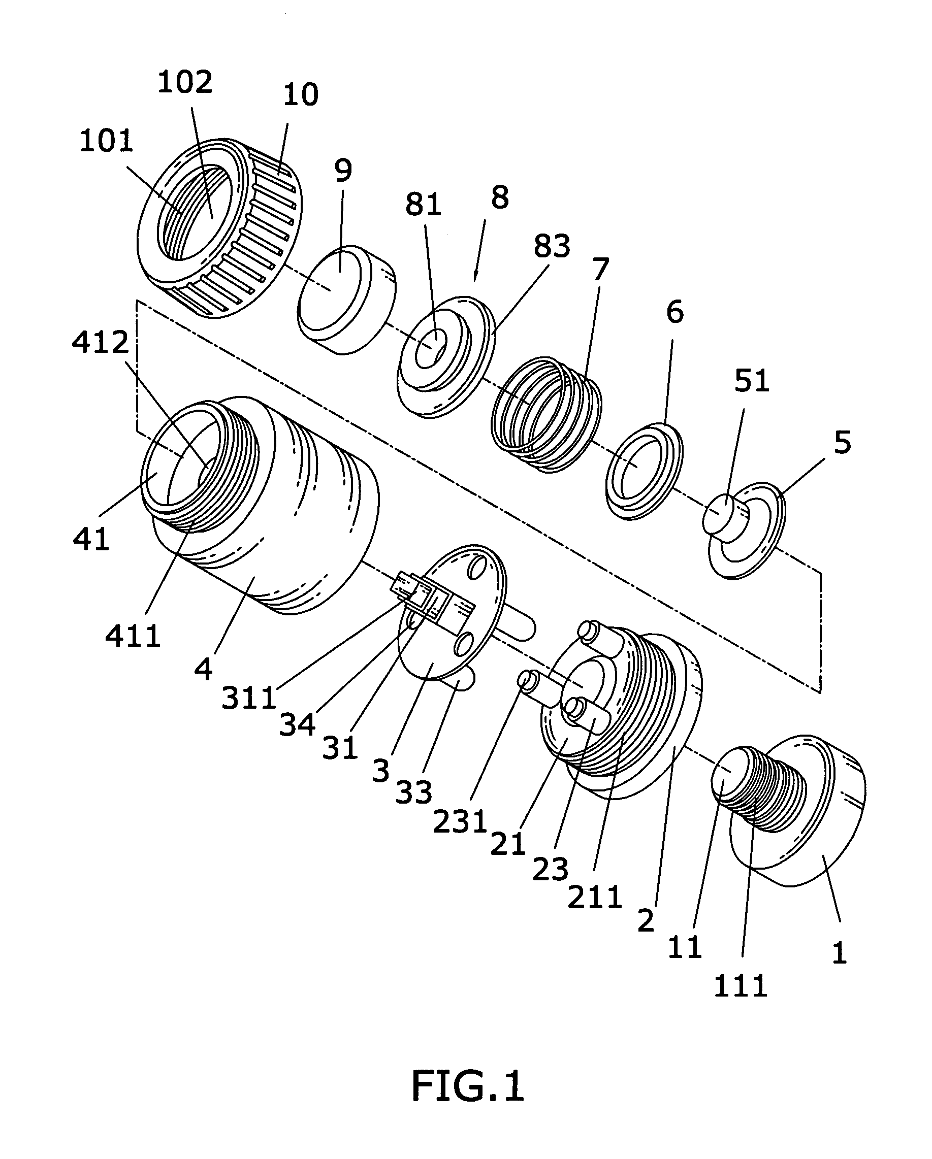
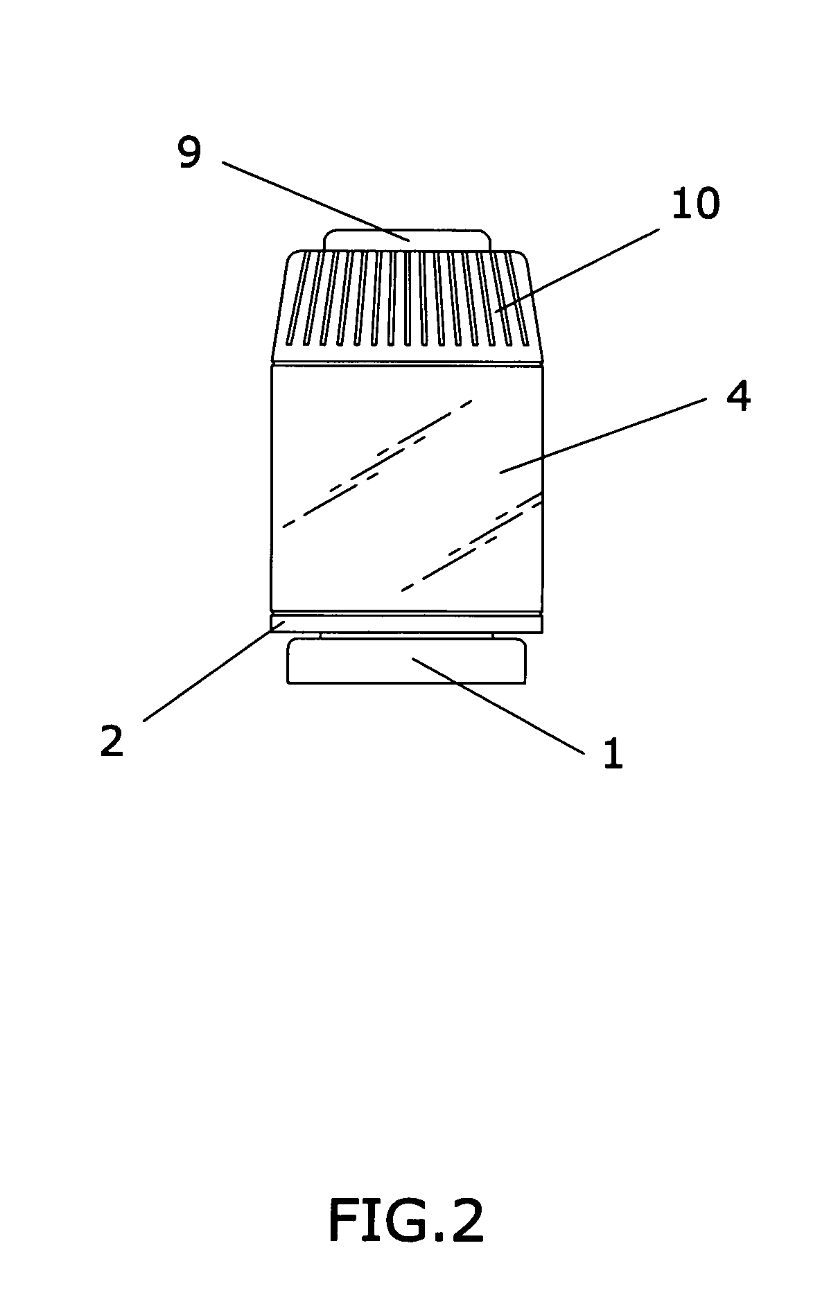
[0029]With reference to FIGS. 1, 2 and 3, the invention comprises:

[0030]a head connecting portion 1 disposed on one end of the light-emitting device, an upper portion 11 of the head connecting portion 1 and a base 2 are integrally formed, in addition, the base 2 has a circuit board 3 fixed on a supporting portion 23 thereof, moreover, the circuit board 3 electrically connects a switch 31, a power outlet 32 for holding battery 35 and at least one luminous body 33 on the circuit board;

[0031]a light permeable portion 4 made of light permeable material sleeves with the...


PUM


Abstract

This invention presented is a detachable light-emitting device having a head connecting portion and a base integrally formed. The base has a circuit board installed thereon, assembled with a light permeable portion. A switch, a power outlet for holding a battery and luminous bodies on the circuit board and placed inside the light permeable portion. The light permeable portion has a bonnet assembled on the upper portion thereof and over a push-button end of the switch. A push-button portion has the lower portion thereof assembled on a power button, a spring is then assembled between the bonnet and the power button for providing a restorable elastic strain for the push-button portion. The assembly of this invention enables the light-emitting device to be easily attached to and detached from an object, thereby adding light-emitting effect and function to the object.

Description

BACKGROUND OF THE INVENTION[0001]1) Field of the Invention[0002]This invention relates to a light-emitting device, in particular, to a device that can be easily attached to and detached from an object, adding light-emitting function to the object, so as to increase practicability of the object.[0003]2) Description of the Prior Art[0004]With the development of science and technology in various industries and commerce, the added values of commodities have been diversified by combining respective singular functions of different objects onto one object in order to meet growing consumer needs. For example, a light-emitting device is commonly attached to an object, such as an umbrella, a baton, a pole, etc., for convenient use.[0005]Generally, a light-emitting device can be used either independently or in combination with another object. Usually, an independently used light-emitting device is like a flashlight, which cannot be installed onto another object; therefore, the practicability t...

Claims


Application Information

Patent Timeline
IPC IPC(8): A45B3/02H01H9/00
CPCA45B3/04H01H11/0006H01H9/182H01H9/06H01H2009/164H01H13/023
Inventor SU, PING-TUNG
Owner THERMO CLINICAL LABSYST
Why Eureka
Try Eureka