
Near-null compensator and figure metrology apparatus for measuring aspheric surfaces by subaperture stitching and measuring method thereof

a technology of subaperture stitching and compensator, which is applied in the direction of geometric properties/aberration measurement, structural/machine measurement, instruments, etc., can solve the problems of inability to meet the requirements of large-caliber aspheric surface reflectors, high manufacturing cost and complexity of such telescopes, and inability to resolve interference fringes on large-caliber aspheric surfaces. , to achieve the effect of improving practicability and maneuverability, simple configuration and compact design

Active Publication Date: 2015-08-25
NAT UNIV OF DEFENSE TECH
View PDF3 Cites 2 Cited by
  • Summary
  • Abstract
  • Description
  • Claims
  • Application Information

AI Technical Summary

Benefits of technology

The present invention aims to address problems with current techniques by providing a small and versatile compensator for measuring aspheric surfaces by subaperture stitching. This invention is easy to use and produces accurate results at a low cost. It provides a simple yet effective method for measuring aspheric surfaces with the figure metrology apparatus.

Problems solved by technology

However, the interference fringes on large caliber aspheric surfaces are too dense to be resolved owning to the departure of large aspheric surfaces which can't be tested within the vertically measuring range of the wavefront interferometer.
Furthermore, the convex aspheric surface reflectors which are used as secondary mirrors in telescopes usually comprise a compensator with aspheric surfaces, in such manner that, the manufacturing cost and complexity of such telescopes are higher.
Due to the limitations of the materials and the manufacturing accuracy of the compensator, it is generally not suitable for large-caliber aspheric surfaces reflector.
Therefore, this method is not applicable to high-slope aspheric surfaces (which has a higher slope of asphericity).
Otherwise, the large aperture aspheric surfaces must be divided into hundreds of subapertures so as to sufficiently reduce the departure of the subapertures thereof, such that the problem of the environmental disturbance and lower measurement repeatability are generated.
Moreover the compensator can't be adjusted to compensate the different ranges of aberrations.
However, the method also can not be applicable to off-axis subapertures on the aspheric surfaces, but it is applicable to rotationally symmetric concave aspheric surfaces.
Utilizing a pair of CGH plates generates the problems of the increase of disturbance orders of diffraction, and reduces efficiency of diffraction.
Besides, when using a pair of counter-rotating phase plates for optical figure metrology, the method for designing the phase function is different from conventional CGH design.
While using a pair of phase plates, the phase function is not well defined by the aspheric and emerging wavefronts because the phase plates do not completely compensate the aberrations of all subapertures.

Method used


Image

  • Near-null compensator and figure metrology apparatus for measuring aspheric surfaces by subaperture stitching and measuring method thereof
  • Near-null compensator and figure metrology apparatus for measuring aspheric surfaces by subaperture stitching and measuring method thereof
  • Near-null compensator and figure metrology apparatus for measuring aspheric surfaces by subaperture stitching and measuring method thereof

Examples


first preferred embodiment

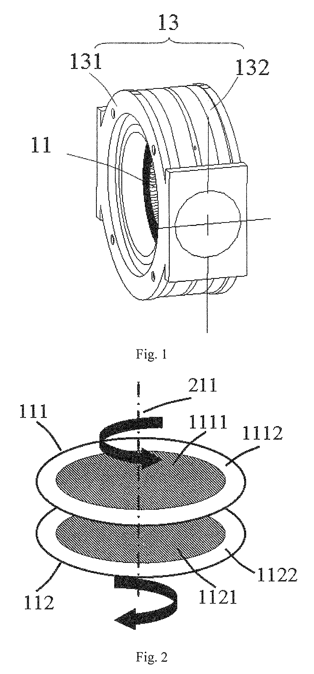
[0054]As shown in FIG. 1 to FIG. 2 of the drawings, a near-null compensator 1 adapted for measuring a aspheric surface via subaperture stitching interferometry according to a preferred embodiment of the present invention is illustrated, wherein the near-null compensator 1 comprises a pair of counter-rotating computer generated holograms (CGH) phase plates 11, defined as a first phase plate 111 and a second phase plate 112. Moreover, each of the phase plates (CGH) 11 comprises a phase function having two terms Z5 (45 degrees to direction of the astigmatism and defocusing) and Z7 (coma and y-tilt) of Zernike polynomials, as shown in below:

[0055] {aZ5=a⁢⁢ρ2⁢sin⁡(2⁢θ)bZ7=b⁡(3⁢⁢ρ2-2)⁢ρsinθ

[0056]wherein, ρ is defined as a pupil coordinate of a normalized radial, and θ is defined as an pupil coordinate of an angular angle, wherein a is a coefficient of Z5 polynomial and b is a coefficient of Z7 polynomial. In other words, the coefficients of Z5 of the two counter-rotating phase plates 11 a...

second preferred embodiment

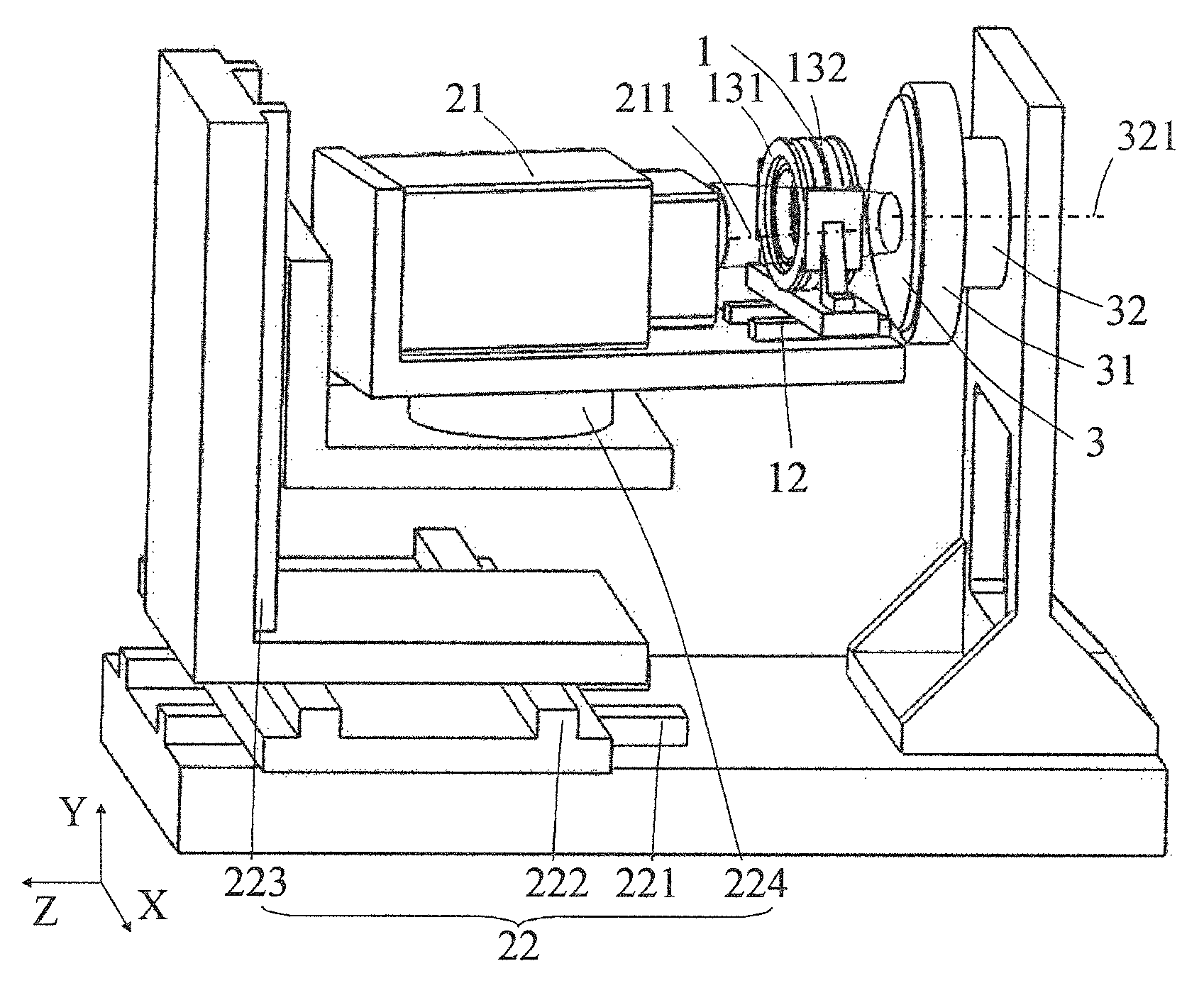
[0081]The convex hyperbolic SiC mirror is embodied as an example. A method for measuring the deviation of the surface figure by subaperture stitching with the figure metrology apparatus according to the second preferred embodiment of the present invention comprising the steps of:

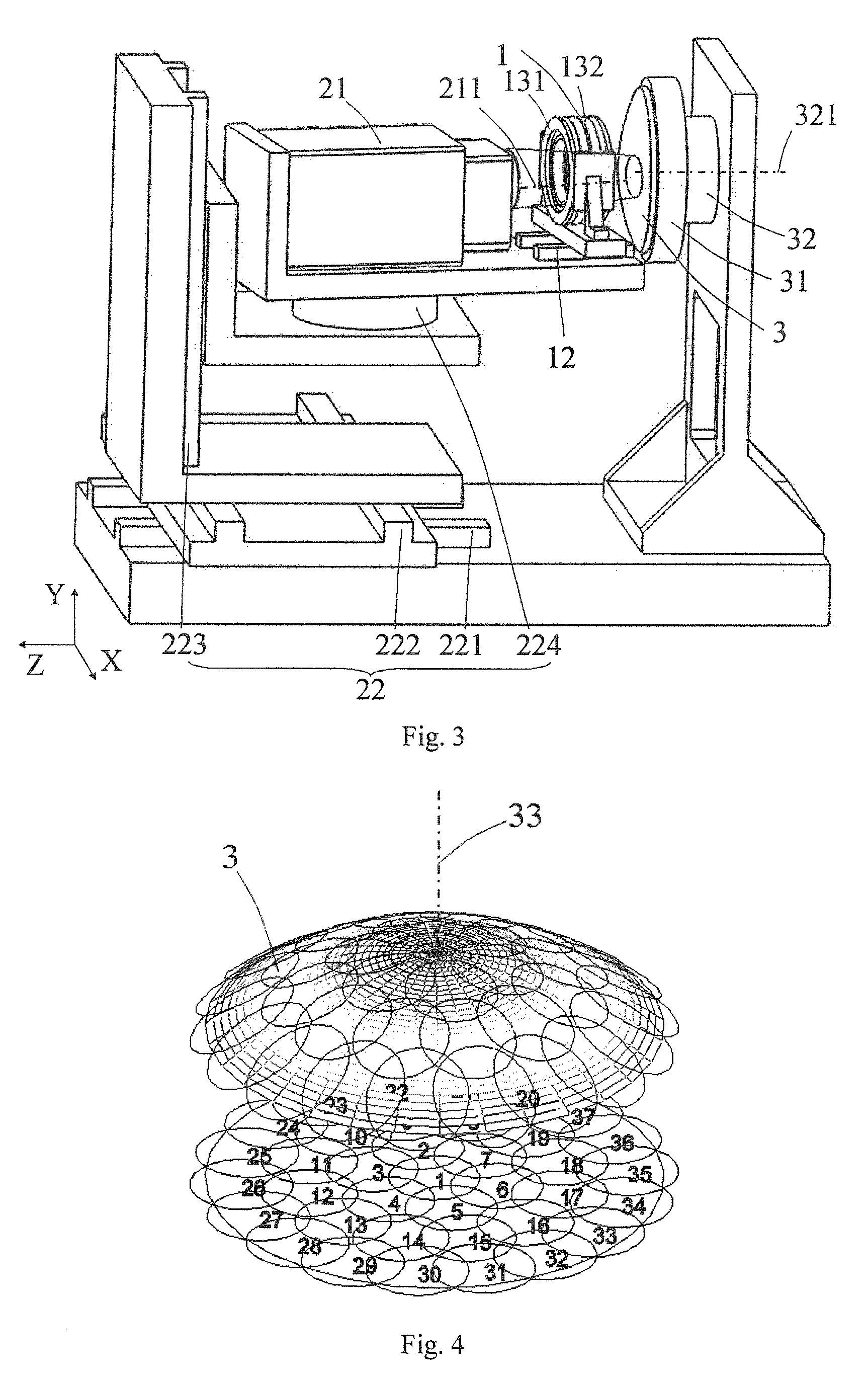
[0082](1) Mount the aspheric test mirror 3 on the test mirror mount 31. As shown in FIG. 4, the aspheric test mirror 3 is divided into a certain number of overlapping subapertures, as shown in FIG. 3.

[0083](2) Measure the central subaperture on the aspheric test mirror 3. By adjusting the mechanical adjustment component for the wavefront interferometer 22, the mechanical adjustment component for the near-null compensator 12, and the mechanical adjustment component for the test mirror 32, wherein the test beam emitted from the wavefront interferometer 21 is aligned to illuminate the central subaperture of the aspheric test mirror 3 after passing through the near-null compensator 1. At this time, the readout f...


PUM


Abstract

A variable near-null compensator for measuring aspheric surfaces by subaperture stitching includes a pair of counter-rotating CGH phase plates, each of the phase plates having a phase function including two terms Z5 and Z7 of Zernike polynomials. The phase plates are mounted on a pair of precision rotary center-through tables, wherein rotational axes of the pair of precision rotary center-through tables coincide with the optical axes of the phase plates. A figure metrology apparatus includes a wavefront interferometer, the test mirror mount, the near-null compensator and the mechanical adjustment components therefor. The optical axis of the near-null compensator coincides with the optical axis of the interferometer. A method for measuring aspheric surfaces by subaperture stitching includes the steps of mounting the test mirror, measuring the subapertures with the figure metrology apparatus, and finally processing the data by stitching.

Description

BACKGROUND OF THE PRESENT INVENTION[0001]1. Field of Invention[0002]The present invention relates to a surface interferometry and more particularly to a variable near-null compensator and a figure metrology apparatus for measuring aspheric surfaces by subaperture stitching interferometry and measuring method thereof.[0003]2. Description of Related Arts[0004]Optical aspheres are widely used in modern optical systems such as telescopes, lithographic objectives and so on. Due to the increase of the requirements for the performances of the modern optical systems, the aspheric surfaces with large caliber and high accuracy become major features in modern optical system. The deviation of the surface figure for an aspheric surface is typically measured by an interferometer. However, the interference fringes on large caliber aspheric surfaces are too dense to be resolved owning to the departure of large aspheric surfaces which can't be tested within the vertically measuring range of the wave...

Claims


Application Information

Patent Timeline
Patent Type & Authority Patents(United States)
IPC IPC(8): G01B9/021G01M5/00G01M11/02G01B9/02
CPCG01B9/021G01B9/02039G01B9/02058G01B9/02085G01M5/005G01M11/025G01M11/0271
Inventor CHEN, SHANYONGDAI, YIFANLI, SHENGYIPENG, XIAOQIANGXIE, CHAOPENG, YANGLIN
Owner NAT UNIV OF DEFENSE TECH
Learn More