
Apparatus and method for redundancy control of duplex switch board

a duplex switch board and redundancy control technology, applied in the direction of generating/distributing signals, frequency-division multiplexes, instruments, etc., can solve the problems of increasing board manufacturing costs additionally, reducing the electric power consumed in the inactive switch board, and difficult to implement the conventional packet switch board

Inactive Publication Date: 2006-05-25
ELECTRONICS & TELECOMM RES INST
View PDF14 Cites 28 Cited by
  • Summary
  • Abstract
  • Description
  • Claims
  • Application Information

AI Technical Summary

Benefits of technology

[0021] It is, therefore, an object of the present invention to provide a redundancy control apparatus of a switch board compatible with an advanced telecommunications computer architecture (ATCA) standard platform without being modified or requiring additional boards although a Shelf or a Backplane is replaced, and a method thereof.

Problems solved by technology

Therefore, a board manufacturing cost increases additionally.
According, it is very difficult to implement the conventional packet switch board because of a complicated structure of a controller for controlling redundancy switching.
Although an electric power consumed in the inactive switch board is reduced by interrupting the system clock applied to the inactive switch board when the opponent switch board is in an active mode and an external processor does not set or check the own state yet, the conventional duplex switch board has a problem of high packet loss by asynchronous clock switching.
However, a hot swap function cannot be provided when redundancy switching.
Therefore, it is difficult to implement the conventional system introduced in U.S. Pub. No. 0128782 A1 to a switch or a router.
As described above, the conventional redundancy controller in the switch board instantly generates packet loss when redundancy switching because each of the switch boards uses a clock provided from an own clock controller.

Method used


Image

  • Apparatus and method for redundancy control of duplex switch board
  • Apparatus and method for redundancy control of duplex switch board
  • Apparatus and method for redundancy control of duplex switch board

Examples


Embodiment Construction

[0036] Reference will now be made in detail to the preferred embodiments of the present invention, examples of which are illustrated in the accompanying drawings.

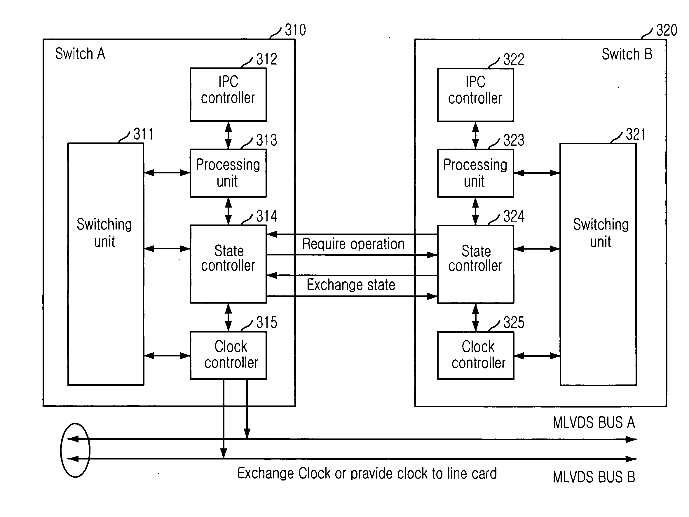
[0037]FIG. 3 is a block diagram illustrating a redundancy controller of duplex switch boards in accordance with a preferred embodiment of the present invention.

[0038] Referring to FIG. 3, the redundancy controller of the duplex switch boards according to the present embodiment includes: switching units 311, 321 for switching data inputted from one of the duplex switch boards to a destination line card; state controllers 314, 324 for controlling a clock state of an opponent switch board among the duplex switch boards; an inter processor communication (IPC) controllers 312, 322 for controlling an inter processor communication (IPC) on an advanced telecommunications computer architecture (ATCA) platform; processing units 313m 323 for controlling the IPC controllers 312, 322 and the state controllers 314, 324; and clock contr...


PUM


Abstract

An apparatus and method for a redundancy control in duplex switch boards in a high speed network system are provided. The apparatus includes: a switching unit for switching data inputted one of the duplex switch boards to a destination line card; a state controlling unit for controlling a clock state of an opponent switch board between the duplex switch boards; an IPC controlling unit for controlling an inter processor communication (IPC) of a platform of the communication network system; a processing unit for controlling the IPC controlling unit and the state controlling unit of the duplex switch boards; and a clock controlling unit for synchronizing a clock between the duplex switch boards.

Description

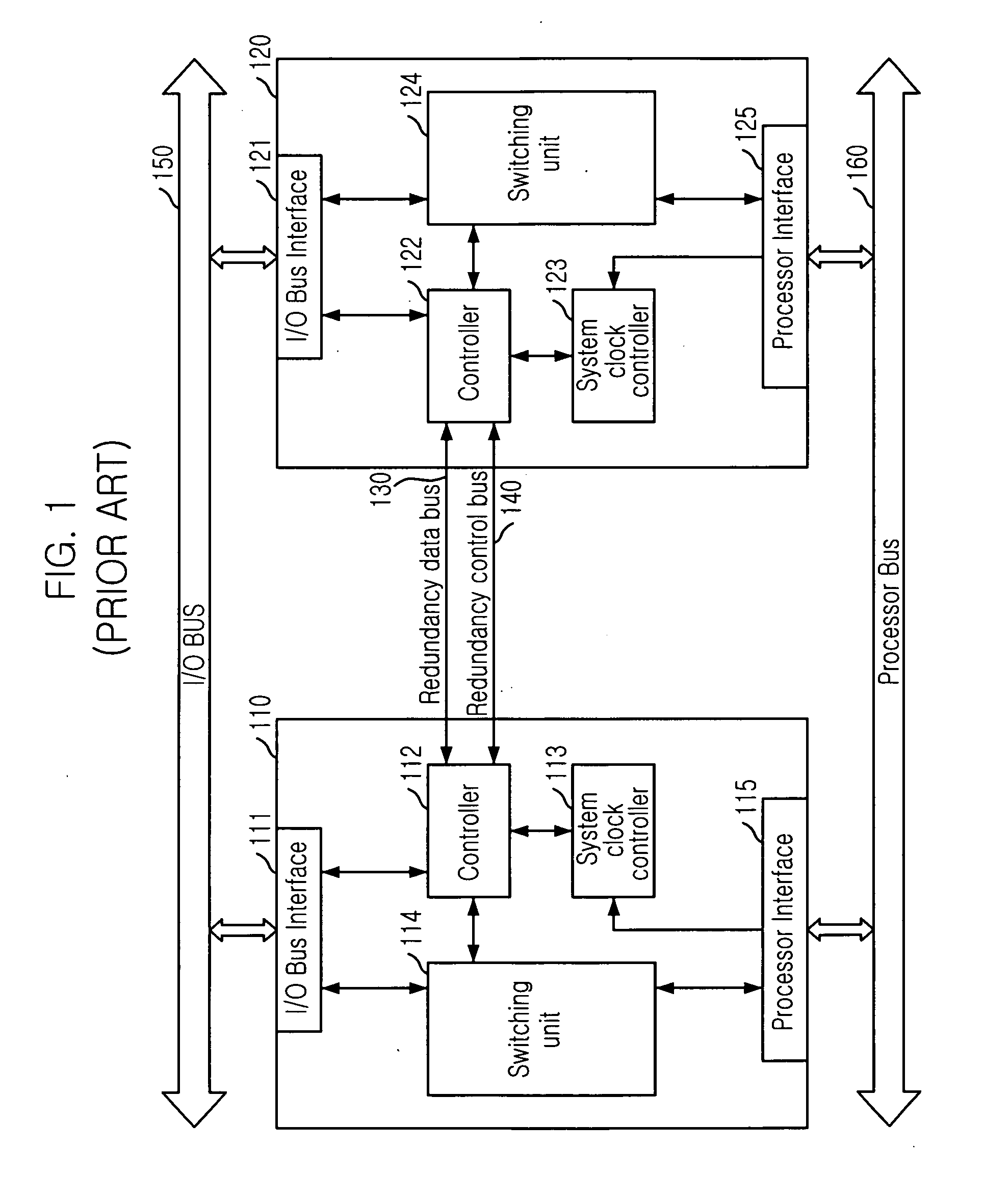
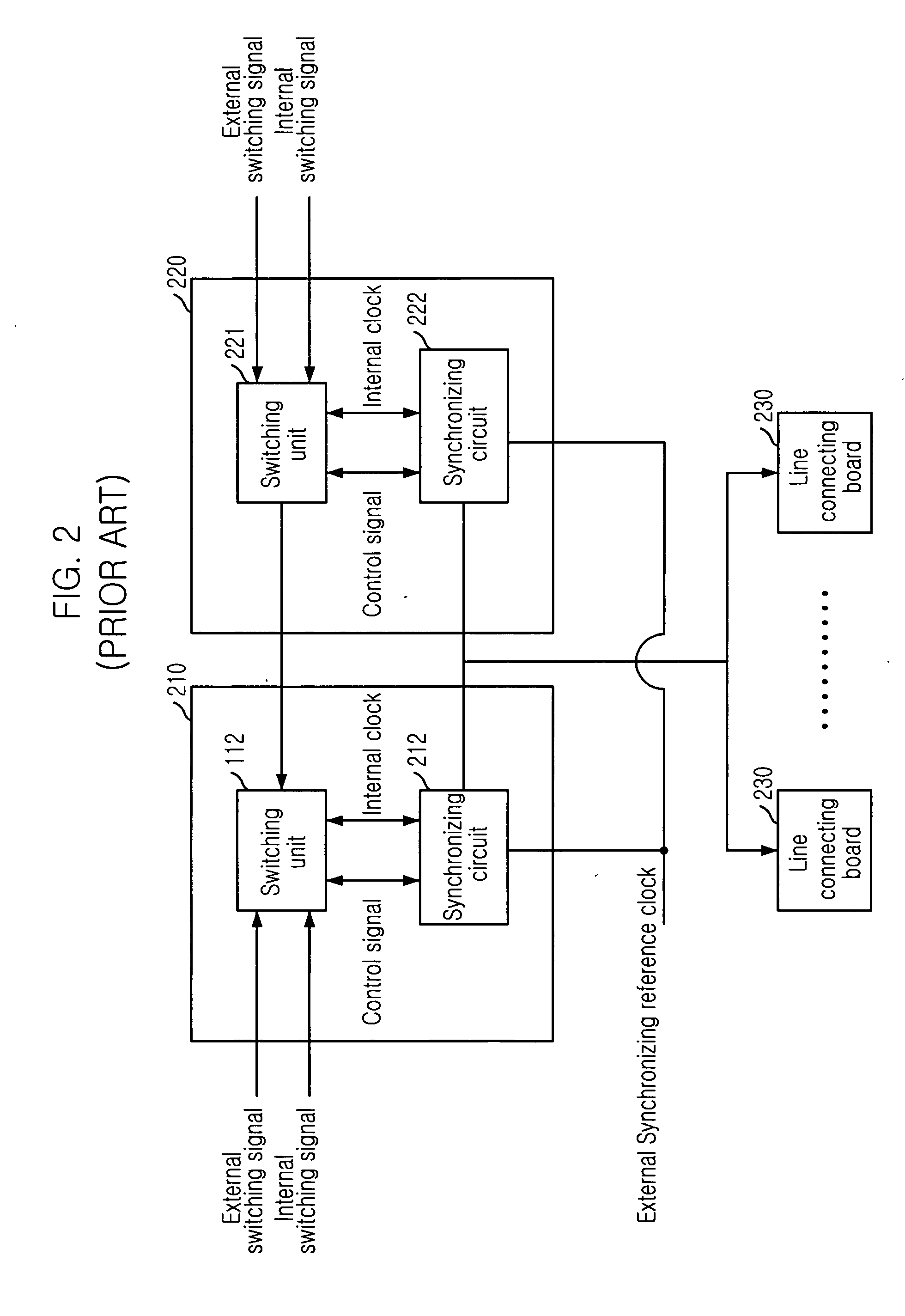
FIELD OF THE INVENTION [0001] The present invention relates to an apparatus for a redundancy control in a high-speed packet switching network and a method thereof; and, more particularly, to a redundancy control apparatus of a duplex switch board for a master clock switching or a redundancy switching in a unit of a plane without packet loss when a switchboard is malfunction, which can be applied to all of advanced telecommunications computer architecture (ATCA) based Shelves or Backplanes without modifying the Shelf or the Backplane, or an edge pin of a switch board according to capacitor variation of a switch or a router, and a method thereof. DESCRIPTION OF THE PRIOR ART [0002] According to population of Internet, data traffic increases, dramatically. Therefore, wide band transmission and high-speed switching function have been demanded. Whenever a backplane including a Shelf is modified, it requires modifying an edge pin in a switch board including a line card, where a high speed...

Claims


Application Information

Patent Timeline
IPC IPC(8): H04J1/16
CPCH04J3/0685H04L7/0008H04L49/1523
Inventor RA, YONGWOOKAHN, BYUNGJUNJUNG, HAE-WON
Owner ELECTRONICS & TELECOMM RES INST
Learn More