
Heavy duty pneumatic tire

a pneumatic tire and heavy duty technology, applied in the direction of vehicle components, transportation and packaging, non-skid devices, etc., can solve the problems of inter-layer peeling among the rubber layers, reverse damage to the wet performance, and uneven wear of the rubber layer, so as to improve the wear resistance and improve the deflective performance. , the effect of favorable us

Inactive Publication Date: 2006-05-18
SUMITOMO RUBBER IND LTD
View PDF2 Cites 52 Cited by
  • Summary
  • Abstract
  • Description
  • Claims
  • Application Information

AI Technical Summary

Benefits of technology

[0012] The object of the present invention is to provide a heavy duty pneumatic tire including block patterns and being capable of improving deflected wear-resisting performances without sacrificing wet grip performances or on-snow performances and that can be favorably used for all seasons.
[0013] Another object of the invention is to provide a heavy duty pneumatic tire capable of restricting degradations in on-snow performances and wet performances accompanying progress of wear to be low.

Problems solved by technology

However, problems are caused in such techniques that non-uniform exposure of the high frictional rubber layer caused through deflected wear.
It will reversely harm the wet performances and causes a inter-layer peeling among the rubber layers.
However, on-snow performances are ensured up to 50% wear in case of winter tires.
It has been found out that degradations in on-snow performances and wet performances accompanying progress of wear can be restricted low in these manners.

Method used


Image

  • Heavy duty pneumatic tire
  • Heavy duty pneumatic tire
  • Heavy duty pneumatic tire

Examples


embodiment 1

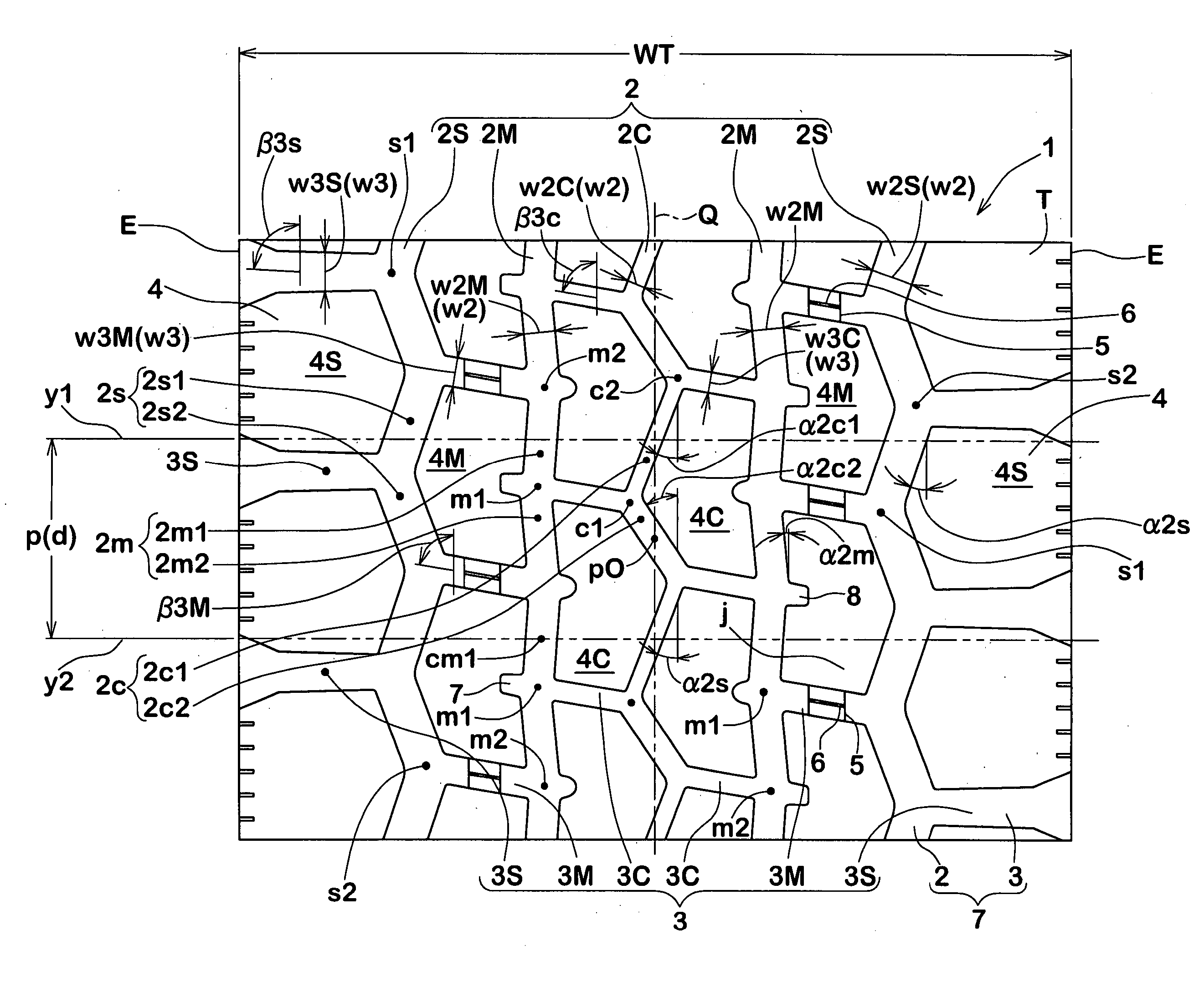
[0149] Heavy duty pneumatic tires with a size of 11R22.5 and with a tread pattern as illustrated in FIG. 1 were manufactured (Table 1) and respective performances have been evaluated. Results of evaluation are indicated in Table 3. In this respect, r coefficients are listed in Table 2.

[0150] Various test conditions as illustrated in Table 1 were as follows. In each of the tests, the rim size was 7.50×22.5, the internal pressure 800 kPa and the vehicle employed was a domestic 10 ton truck 2-D vehicle (half loaded on the front half of the truck box).

(1) WET Turning Performances

[0151] Place: Okayama Test Course of Sumitomo Rubber Industries, Ltd. Method: Lap times of a single lap on the course of a radius of 30 m in a wet condition were represented as reciprocates of ratios with respect to the Comparative Example 1. The value of the Comparative Example 1 was defined to be 100, and the larger the value is, the more favorable it is.

(2) WET Traction Performances

Place: Okayama Test...

embodiment 2

[0158] Heavy duty pneumatic tires with a size of 11R22.5 and with a tread pattern as illustrated in FIG. 1 were manufactured and respective performances have been evaluated. Results of evaluation are indicated in Table 4. Various test conditions as illustrated in Table 4 were as follows. In each of the tests, the rim size was 7.50×22.5, the internal pressure 800 kPa and the vehicle employed was a domestic 10 ton truck 2-D4 vehicle (half loaded on the front half of the truck box).

(1) WET Grip Performances

Place: Okayama Test Course of Sumitomo Rubber Industries, Ltd.

[0159] Method: Lap times of a single lap on the course of a radius of 30 m in a wet condition were represented as reciprocates of ratios with respect to the Comparative Example 1. The value of the Comparative Example 1 was defined to be 100, and the larger the value is, the more favorable it is.

(2) Deflected Wear Resisting Performances

Running distance: 40,000 km

[0160] Method of evaluation: 40,000 km was traveled ...

embodiment 3

[0162] Heavy duty pneumatic tires with a size of 11R22.5 and with a tread pattern as illustrated in FIG. 1 were manufactured according to specifications of Table 5 and on-snow performances and wet performances of the respective sample tires were evaluated respective in a new condition, a 50% wear condition, and a 90% wear condition, and the results are indicated in Table 5.

[0163] In this respect, respective values of EL00, EL50, and EL90 in Table 5 are represented in the Comparative Example 1 as indices with the length L1 of the total axial edge component of a new product of Comparative Example 1 being defined as 100. Similarly, such values are represented in the Comparative Example 2 as indices with the length L2 of the total axial edge component of a new product of Comparative Example 2 being defined as 100, in Example 1 as indices with the length L3 of the total axial edge component of a new product of Example 1 being defined as 100, and in the Example 3 as indices with the leng...


PUM


Abstract

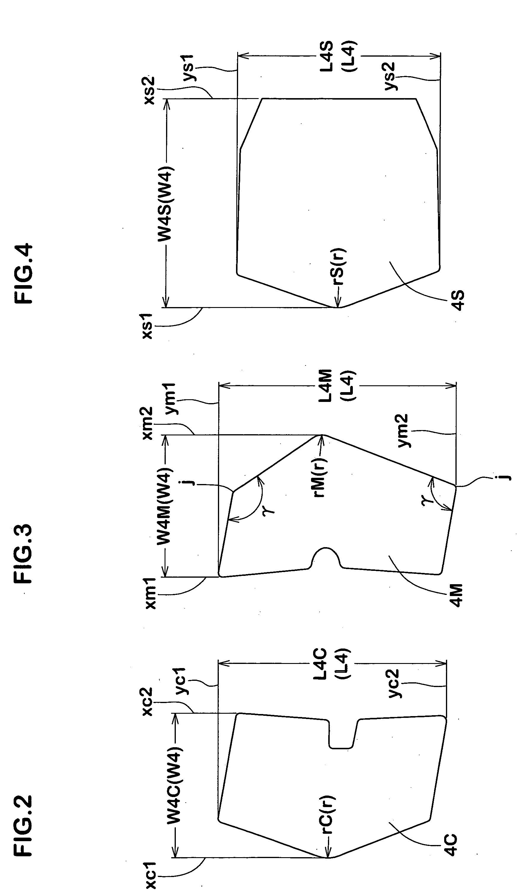
It aims to provide a heavy duty pneumatic tire with block patterns and capable of improving deflected wear resisting performances without sacrificing wet grip performances or on-snow performances and that can particularly be favorably used for all seasons. The present invention comprises block patterns employing at least three types of blocks 4 comprised of central blocks 4C delimited by the central longitudinal groove 2M, the intermediate longitudinal grooves 2M, and the central lateral grooves 3C, intermediate blocks 4M delimited by the intermediate longitudinal grooves 2M, the outer longitudinal grooves 2S and the intermediate lateral grooves 3M, and outer blocks 4S that are delimited by outer longitudinal grooves 2S, outer lateral grooves 3S that extend from this outer longitudinal grooves 2S to the tread ends E, and wherein longitudinal length ratios (L4 / W4) of blocks 4, groove width ratios of longitudinal grooves and lateral grooves (w2 / w3), maximum widths of blocks, minimum widths of blocks and ratios thereof (W4max / W4min), and circumferential edge components and tire axial edge components and ratios thereof (EC / EL) at respective stages of wear are defined to be within specified ranges.

Description

BACKGROUND OF THE INVENTION [0001] The present invention relates to a heavy duty pneumatic tire of improved deflected wear resisting properties achieved by improving tread patterns. [0002] Tires that can be used for all seasons are being desirable for use as heavy duty pneumatic tires that are employed for heavy vehicles such as trucks and busses. Such all-season heavy duty pneumatic tires are required to maintain high wet grip performances and steering stability performances for the aim of safe running on road surfaces of various conditions. For this purpose, block patterns are mainly employed as tread patterns in many cases. [0003] On the other hand, it is the case with tires with block patterns, especially heavy duty pneumatic tires that large shear force acts on a first contacting side and last contacting side in a rotating direction during running or braking and sliding friction is generated between the tire and the road surface. So-called heel and toe wear (referred to as H / T ...

Claims


Application Information

Patent Timeline
Patent Type & Authority Applications(United States)
IPC IPC(8): B60C11/11
CPCB60C11/0306B60C11/0309B60C11/1369Y10S152/902
Inventor TAKAHASHI, SHINGOTSUDA, SATOSHI
Owner SUMITOMO RUBBER IND LTD
Learn More