
Multilayer type printed-wiring board and method of measuring impedance of multilayer type printed-wiring board

a printed wiring board and multi-layer technology, applied in the direction of measuring leads/probes, inspection/indentification of circuits, instruments, etc., can solve the problems of inability to transmit exchange signals between the cpu module and the memory module, and the impedance is greater or smaller, so as to achieve easy and simple fashion

Inactive Publication Date: 2006-05-11
OKUBO TAKAHARU +3
View PDF7 Cites 6 Cited by
  • Summary
  • Abstract
  • Description
  • Claims
  • Application Information

AI Technical Summary

Benefits of technology

[0007] In view of the above circumstances, it is therefore an object of the present invention to provide a novel multilayer type printed-wiring board adapted to measuring the impedance of the data transmission wire pattern on the manufacturing floor in an easy and simple fashion.
[0008] Another object of the present invention is to provide a multilayer type printed-wiring board comprising a pair of data transmission wire patterns arranged at the opposite sides of the inner layer substrate and adapted to measuring the impedances of the two data transmission wire patterns in a single measuring operation to improve the efficiency of the measurement process.
[0018] Preferably, the clearance between said impedance measuring wire pattern of said multilayer type printed-wiring board and any adjacent wiring pattern is not less that twice of the pattern width of said impedance measuring wire pattern so as not to have any interference of the adjacent wiring pattern.
[0019] Preferably, the wiring pattern arranged around the impedance measuring wire pattern of the multilayer type printed-wiring board is a GND pattern connected to said GND land section by way of a plurality of through holes so as to eliminate any inductance component.
[0021] Thus, with a multilayer type printed-wiring board according to the invention, since an impedance measuring wire pattern is arranged in the layer of the data transmission wire pattern and the pattern width that affects the impedance of the device is made equal to that of the data transmission wire pattern so that the impedance of the data transmission wire pattern can be measured accurately by means of a method of measuring the impedance of a multilayer type printed-wiring board according to the invention. The impedance of a multilayer type printed-wiring board can be measured accurately by means of a TDR (time domain reflectometer) unit when the impedance measuring wire pattern has a pattern length not smaller than about 30 mm.

Problems solved by technology

However, some of the data transmission wire patterns of the printed-wiring boards shipped from manufacturing plants after the completion of the manufacturing process can show discrepancies between the design values and the actual values due to various reasons including the conditions for etching copper foils in the data transmission wire patterns to consequently give rise to an impedance greater or smaller than the design value.
When the impedance does not agree with the design value, it is no longer possible to transmit exchange signals between the CPU module and the memory module.

Method used


Image

  • Multilayer type printed-wiring board and method of measuring impedance of multilayer type printed-wiring board
  • Multilayer type printed-wiring board and method of measuring impedance of multilayer type printed-wiring board
  • Multilayer type printed-wiring board and method of measuring impedance of multilayer type printed-wiring board

Examples


Embodiment Construction

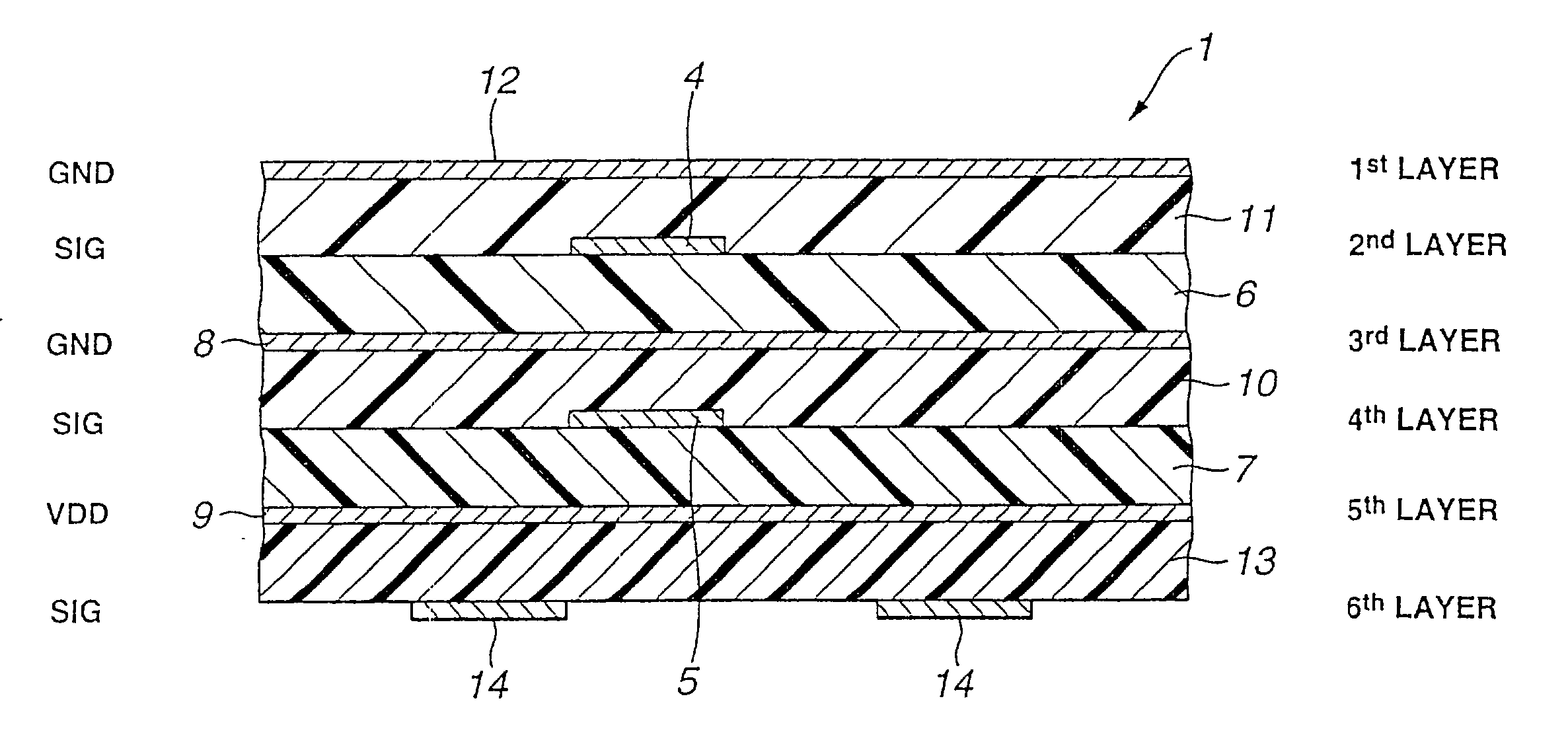
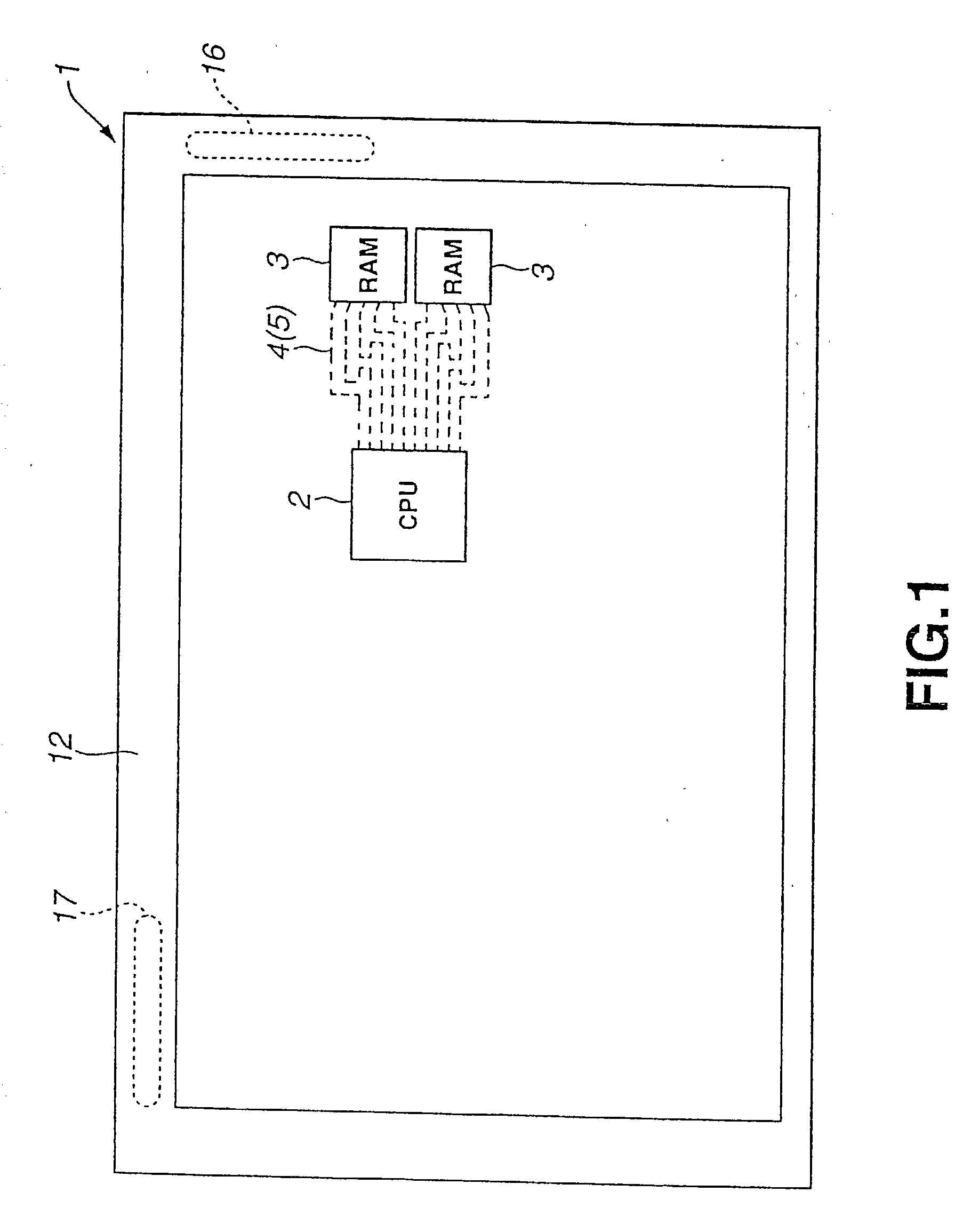
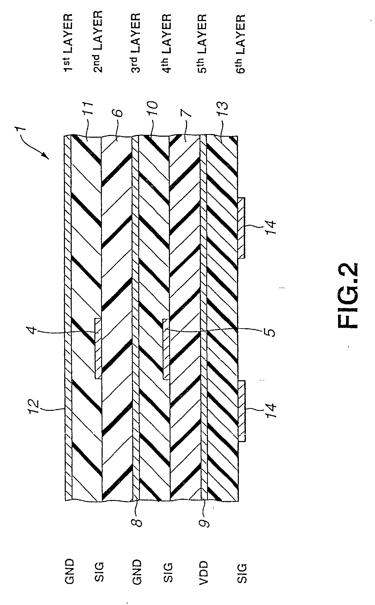
[0029] Now, a multilayer type printed-wiring board and a method of measuring the impedance of a multilayer type printed-wiring board according to the invention will be described in greater detail by referring to the accompanying drawing. FIG. 1 is a schematic plan view of an embodiment of multilayer type printed-wiring board according to the invention. The multilayer type printed-wiring board 1 has a total of six electro-conductive layers and is adapted to be used in a game machine for home use.

[0030] Referring to FIG. 1, the multilayer type printed-wiring board 1 comprises a CPU (central processing unit) module 2 and a pair of memory modules 3, 3 to be used for the CPU module 2 that are arranged on one of the opposite sides of the multilayer type printed-wiring board 1. The CPU module 2 has an operating frequency higher than that of any ordinary CPU and is adapted to operate at a frequency above about 290 MHz or more and typically between 300 MHz and 400 MHz so that it may be able...


PUM


Abstract

The impedance of a newly manufactured data transmission wire pattern can be measured easily and accurately. A multilayer type printed-wiring board 1 comprises a pair of data transmission wire patterns 4, 5 arranged between a CPU module 2 and a memory module 3 on respective inner layer substrates 6, 7, impedance measuring wire patterns 21 and 22 arranged respectively in the layers same as those of the data transmission wire patterns 4, 5, a prepreg layer 11 arranged on the impedance measuring wire patterns 21, 22, land sections 23, 23 for signals arranged on the prepreg layer 11 and electrically connected to the impedance measuring wire patterns 21, 22 so as to be brought into contact with the signal terminal 41 of a probe 40 and a GND land section 24 also arranged on the prepreg layer 11 and electrically connected to the impedance measuring wire patterns 21, 22 so as to be brought into contact with the GND terminal 42 of the probe 40, the impedance measuring wire patterns 21, 22 having a pattern length not smaller than 30 mm that is the minimal length required for use with a TDR unit and a pattern width same as that of the data transmission wire patterns 4, 5.

Description

BACKGROUND OF THE INVENTION [0001] 1. Field of the Invention [0002] This invention relates to a multilayer type printed-wiring board provided with a checking coupon for measuring the characteristic impedance of the data transmission wire pattern arranged between a CPU module and a memory module. [0003] 2. Related Background Art [0004] Electronic devices such as game machines for home use and mobile telephone sets typically comprises a printed-wiring board arranged in the cabinet thereof and a CPU (central processing unit) module and a main memory module are mounted there along with other modules. The CPU module and the memory module are connected to each other by a data transmission wire pattern arranged on the printed-wiring board. [0005] Meanwhile, the data transmission wire pattern of a printed-wiring board have to be designed in such a way that the impedance of the wire pattern shows a value that corresponds to the impedance specified for the CPU module and the memory module mou...

Claims


Application Information

Patent Timeline
Patent Type & Authority Applications(United States)
IPC IPC(8): H05K1/16G01R31/28G01R1/06H05K1/02H05K1/11H05K3/46
CPCG01R31/2812G01R31/2818G01R31/2822H05K1/0268
Inventor OKUBO, TAKAHARUISHIKAWA, TAKASHIFUJITA, HIROYUKIHORIE, SHOJI
Owner OKUBO TAKAHARU
Learn More