
Speaker system, audio amplifier and audio system

a speaker system and amplifier technology, applied in the direction of transducer details, electrical transducers, electrical apparatus, etc., can solve the problems of loss of the frequency characteristic balance between the speaker unit and the bass reflex port, and difficulty in obtaining a flat characteristic over a wide low frequency band range, so as to achieve no loss, flat frequency characteristic, and accent the effect of low-pitched sound

Inactive Publication Date: 2006-05-04
YAMAHA CORP
View PDF4 Cites 11 Cited by
  • Summary
  • Abstract
  • Description
  • Claims
  • Application Information

AI Technical Summary

Benefits of technology

[0014] To avoid the above-mentioned inconveniences, the present invention is arranged to shift respective phases of low-frequency signals to be input to the individual speakers and thereby prevent sounds from assuming opposite phases, even in the above-mentioned frequency band range causing an opposite-phase state, because the phases have been shifted in advance according to the invention. In this way, the present invention can avoid an undesired dip in the frequency characteristic.
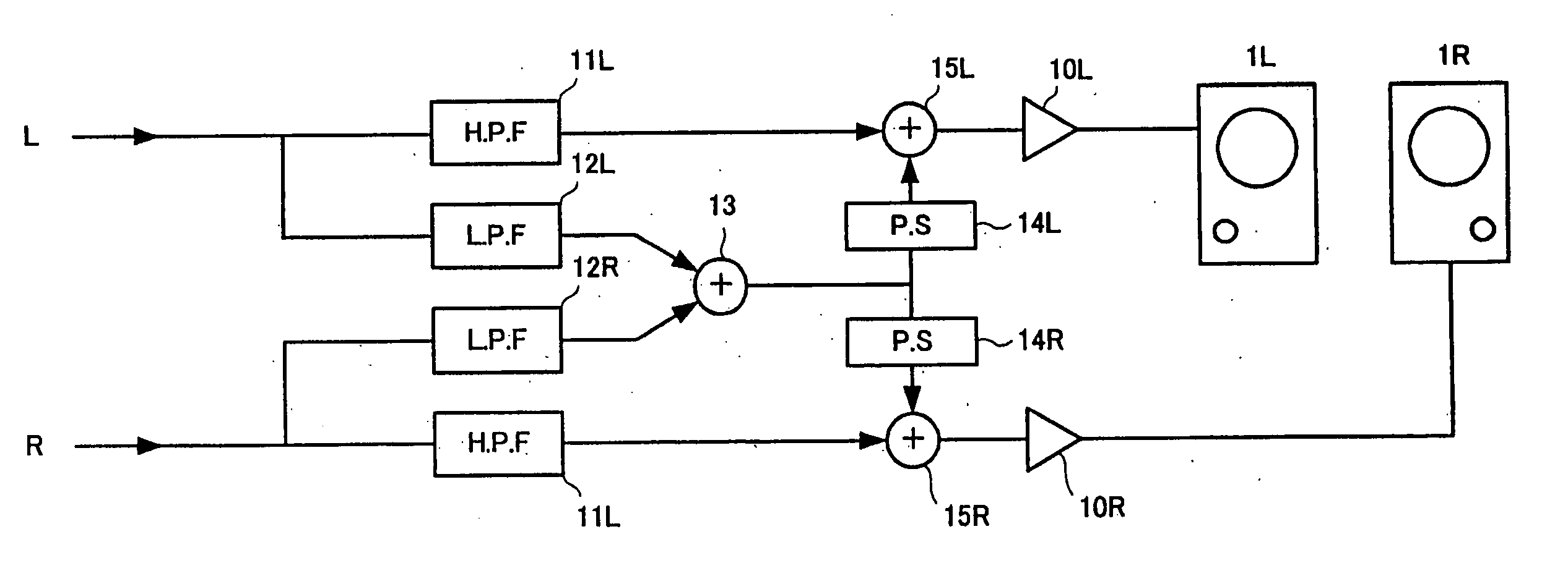
[0015] Particularly, in the present invention, the low-frequency signal is shifted, for each of the plurality of channels, with a characteristic corresponding to a combination of phase characteristics of the cabinets of the speakers connected to the other channels than the channel in question (e.g., in the case of a 2-channel system, with a characteristic of the other channel, or in the case of a 5-channel system, with a characteristic corresponding to a combination of phase characteristics of the other four channels). In this way, the present invention allows low-frequency signals of all of the channels to agree with each other in phase and can thereby accentuate a low-pitched sound with no loss.
[0016] Namely, according to the present invention, it is possible to achieve a flat frequency characteristic over a wide low frequency band range by employing a plurality of speakers each with a resonance-type cabinet and differentiating the low-band resonance frequency between these speakers.

Problems solved by technology

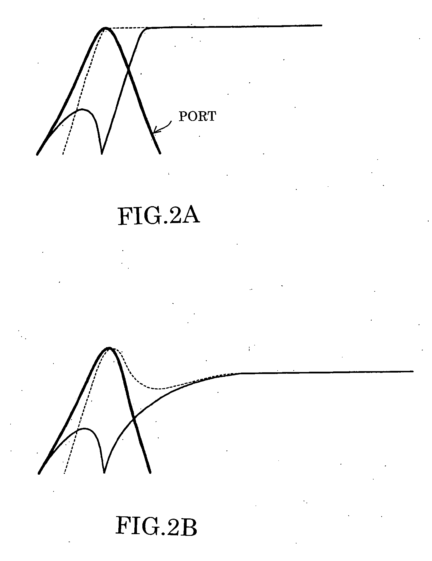
Particularly, where the cabinet is designed to achieve strong resonance, however, balance in frequency characteristic between the speaker unit and the bass reflex port would be lost as seen in FIG. 2B, which would often make it difficult to obtain a flat characteristic over a wide low frequency band range.

Method used


Image

  • Speaker system, audio amplifier and audio system
  • Speaker system, audio amplifier and audio system
  • Speaker system, audio amplifier and audio system

Examples


Embodiment Construction

[0027]FIGS. 3A and 3B are views of speaker systems according to embodiments of the present invention. In each of FIGS. 3A and 3B, one speaker system comprises a plurality of full-range speakers. In this specification, a plurality of speaker units (tweeter, woofer, etc.) housed in a single cabinet will be referred to simply as a “speaker” and a combination or set of a plurality of such speakers will be referred to as a “speaker system”, whereas such a plurality of speaker units housed in a single cabinet are conventionally called a “speaker system”.

[0028] Specifically, FIG. 3A shows a speaker system for stereo two channels or virtual-surround two channels, where one of the speakers is for the left (L) channel while the other speaker is for the right (R) channel. FIG. 3B shows a 5.1-channel surround speaker system, which comprises speakers for the left (L) channel, center (C) channel, right (R) channel, surround left (SL) channel, surround right (SR) channel. Where such a 5.1-channel...


PUM


Abstract

Speaker system is constructed of a plurality of speakers each including a bass-reflex type cabinet. The speaker system is designed to differentiate a low-band resonance frequency between the speakers by differentiating inner cubic capacities of the speaker cabinets from each other. Audio signal of a different channel is input to each of the speakers, and only low-frequency signals of all of the channels are added together so that the added result is supplied to all of the speakers. Thus, using the differentiated low-band resonance frequencies, the speaker system permits reproduction of low-pitched sounds with a flat characteristic.

Description

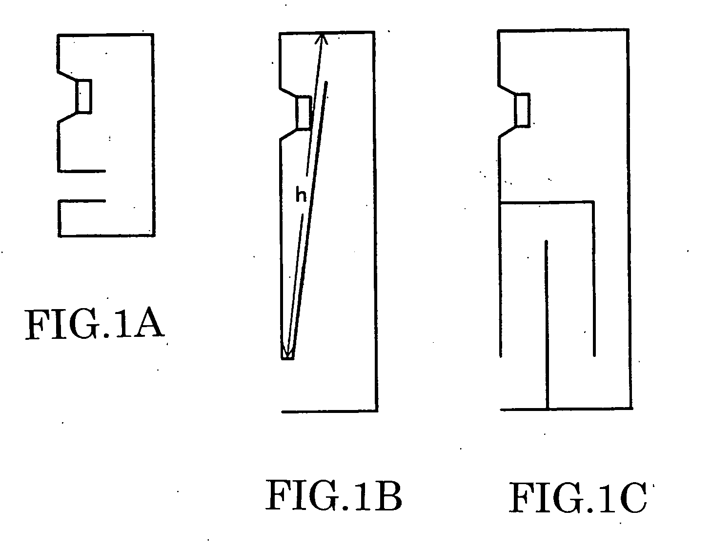
BACKGROUND OF THE INVENTION [0001] The present invention relates to an improved speaker system and audio system which allow a low-pitched sound to be output with a flat characteristic. [0002] In the field of speakers including a speaker unit housed in a cabinet (commonly called “speaker systems”), there have been proposed various internal structures (so-called “enclosures”) of the cabinets which, in order to enhance a low-pitched-sound reproduction efficiency, can not only lower a low-band resonance frequency f0 of the speaker unit itself but also allow low-pitched sounds to be output in an accentuated fashion. One example of such internal structures of the speaker cabinets is proposed in “Encyclopedia of Speaker & Enclosure” published in 1999 by Seibundo Shinko Sha under editorial supervision by Saeki Tamon. [0003]FIGS. 1A-1C are views showing examples of interior structures of speaker cabinets. Specifically, FIG. 1A shows the interior structure of a bass-reflex type cabinet, which...

Claims


Application Information

Patent Timeline
Patent Type & Authority Applications(United States)
IPC IPC(8): H04R1/40H03G5/00
CPCH04R1/2819H04S1/002H04S2400/01H04S2400/07
Inventor NORO, MASAO
Owner YAMAHA CORP
Learn More