
MIMO system and method

Inactive Publication Date: 2006-05-04
SAMSUNG ELECTRONICS CO LTD
View PDF5 Cites 52 Cited by
  • Summary
  • Abstract
  • Description
  • Claims
  • Application Information

AI Technical Summary

Benefits of technology

[0013] However, a scheme for feeding back a weight matrix may increase the number of calculations in a receiver side and decrease channel efficiency due to enormous feedback information of the weight matrix.
[0015] Accordingly, the present invention has been made to solve at least the above-mentioned problems occurring in the prior art, and it is an object of the present invention to provide an MIMO system and an MIMO method, in which an optimal antenna coordination is determined based on feedback information from a reception side, thereby maximizing transmission efficiency.
[0016] It is another object of the present invention to provide an MIMO system and an MIMO method, in which different antenna coordinations are applied according to each sub-channel, thereby increasing diversity gain without a change in a data rate.
[0017] It is further another object of the present invention to provide an MIMO system and an MIMO method, in which a reception side feeds back a weight matrix for determining an optimal antenna coordination in the form of a corresponding index, thereby improving channel efficiency.
[0018] It is still another object of the present invention to provide an MIMO system and an MIMO method, in which only a weight matrix for one antenna coordination is used for automatically calculating for an optimal weight matrix for other antenna coordinations with reference to a relation between a plurality of antenna coordinations, thereby improving transmission reliability without increasing the calculation amount and feedback information of the weight matrix.

Problems solved by technology

However, a scheme for feeding back a weight matrix may increase the number of calculations in a receiver side and decrease channel efficiency due to enormous feedback information of the weight matrix.
Therefore, both the calculation amount and the feedback information of the weight matrix are doubled, so that channel efficiency may deteriorate greatly.

Method used


Image

  • MIMO system and method
  • MIMO system and method
  • MIMO system and method

Examples


Embodiment Construction

[0026] Hereinafter, a preferred embodiment according to the present invention will be described with reference to the accompanying drawings. It should be noted that the similar components are designated by similar reference numerals although they are illustrated in different drawings. Also, in the following description, a detailed description of known functions and configurations incorporated herein will be omitted when it may obscure the subject matter of the present invention.

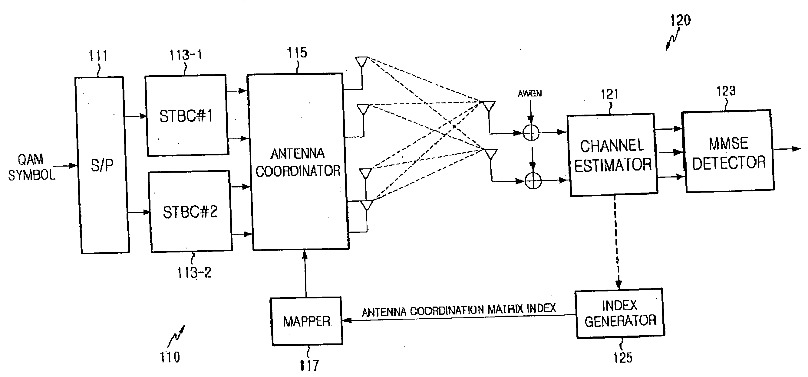
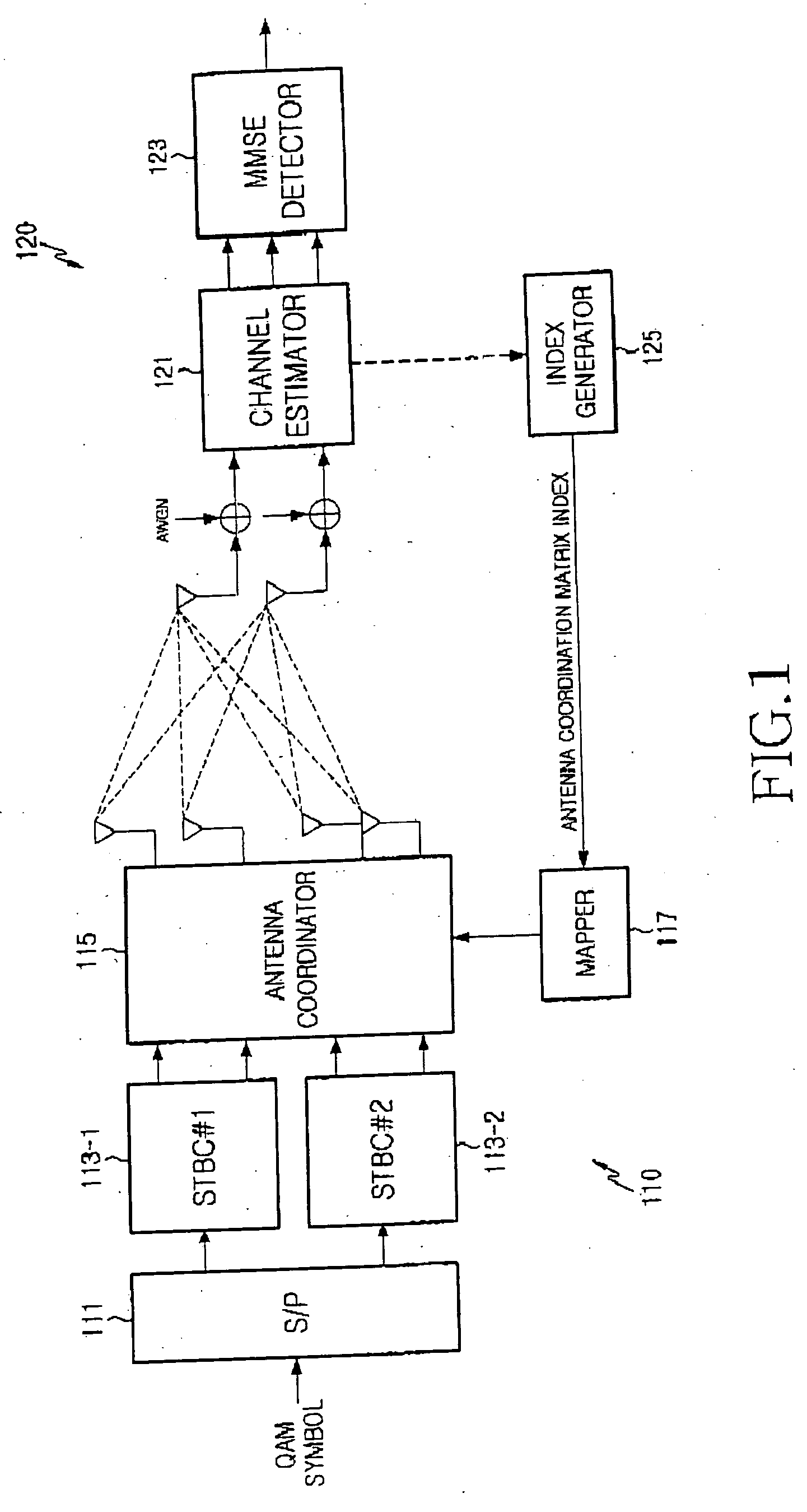
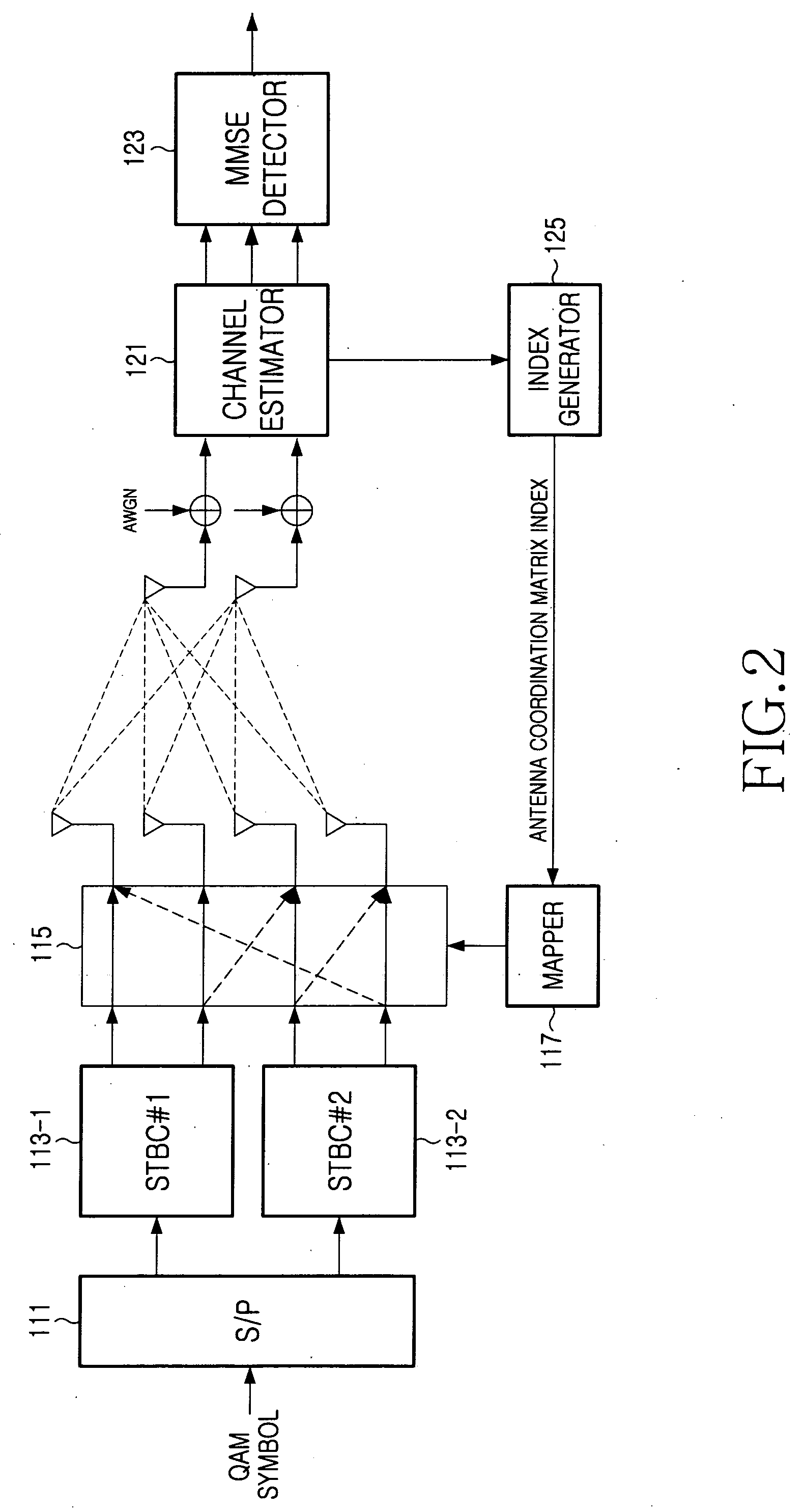
[0027]FIG. 1 is a block diagram illustrating the construction of an MIMO system to which the present invention is applied. The MIMO system includes a transmitter 110 having four transmit antennas and a receiver 120 having two receive antennas.

[0028] The transmitter 110 includes a serial-to-parallel converter 111, Space-Time Block Coders (STBCs) 113-1 and 113-2, an antenna coordinator 115, and a mapper 117. The serial-to-parallel converter 111 performs a serial-to-parallel conversion for an input modulation ...


PUM


Abstract

There is provided a Multi-Input Multi-Output (MIMO) communication system including a transmitter for combining at least four transmit antennas according to each of at least two sub-channels, and transmitting space-time-coded signals and at least one receiver for receiving the signals through at least two antennas, wherein the receiver includes an antenna coordination information generator for generating and feeding back optimal transmit antenna coordination information according to said each sub-channel by means of the received signals, and the transmitter includes an antenna coordination controller for controlling coordinations of the transmit antennas according to each sub-channel based on the transmit antenna coordination information fed back from the receiver.

Description

PRIORITY [0001] This application claims priority to applications entitled “Improved MIMO System and Method” filed in United States Patent and Trademark Office on Nov. 2, 2004 and assigned U.S. provisional application Ser. No. 60 / 624,274 and filed in the Korean Intellectual Property Office on Feb. 21, 2005 and assigned Serial No. 2005-14201, the contents of which are incorporated herein by reference.BACKGROUND OF THE INVENTION [0002] 1. Field of the Invention [0003] The present invention relates to a wireless communication system, and more particularly to a Multi-Input Multi-Output (MIMO) communication system using a rate 2 Space-Time Code (STC). [0004] 2. Description of the Related Art [0005] In the next generation mobile communication system, an MIMO system using a multiple transmit / receive antenna is gathering strength as an important issue for standardization in transmission schemes for high speed data transmission. A data transmission scheme using an MIMO system may be classifie...

Claims


Application Information

Patent Timeline
IPC IPC(8): H04L1/02
CPCH04L1/0643H04L1/0693H04B7/0404H04B7/0413
Inventor JUNG, YOUNG-HOCHUNG, JAE-HAKNAM, SEUNG-HOONROH, WON-ILOH, JEONG-TAECHAE, CHAN-BYOUNGKO, KYUN-BYOUNG
Owner SAMSUNG ELECTRONICS CO LTD
Learn More