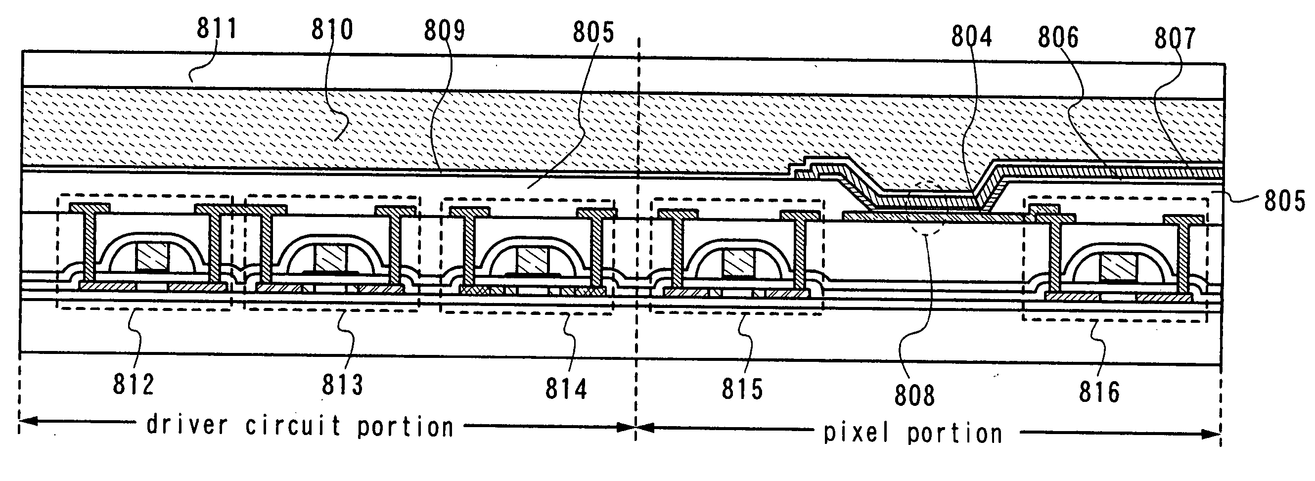
Semiconductor device and method for manufacturing the same
a technology of semiconductors and semiconductors, applied in the field of semiconductor devices, can solve the problems of not working effectively in suppressing current, not working effectively in preventing deterioration, and almost impossible to obtain a field effect mobility of 10 cmsup>2/sup>/vsec or mor
- Summary
- Abstract
- Description
- Claims
- Application Information
AI Technical Summary
Benefits of technology
Problems solved by technology
Method used
Image
Examples
embodiment mode 1
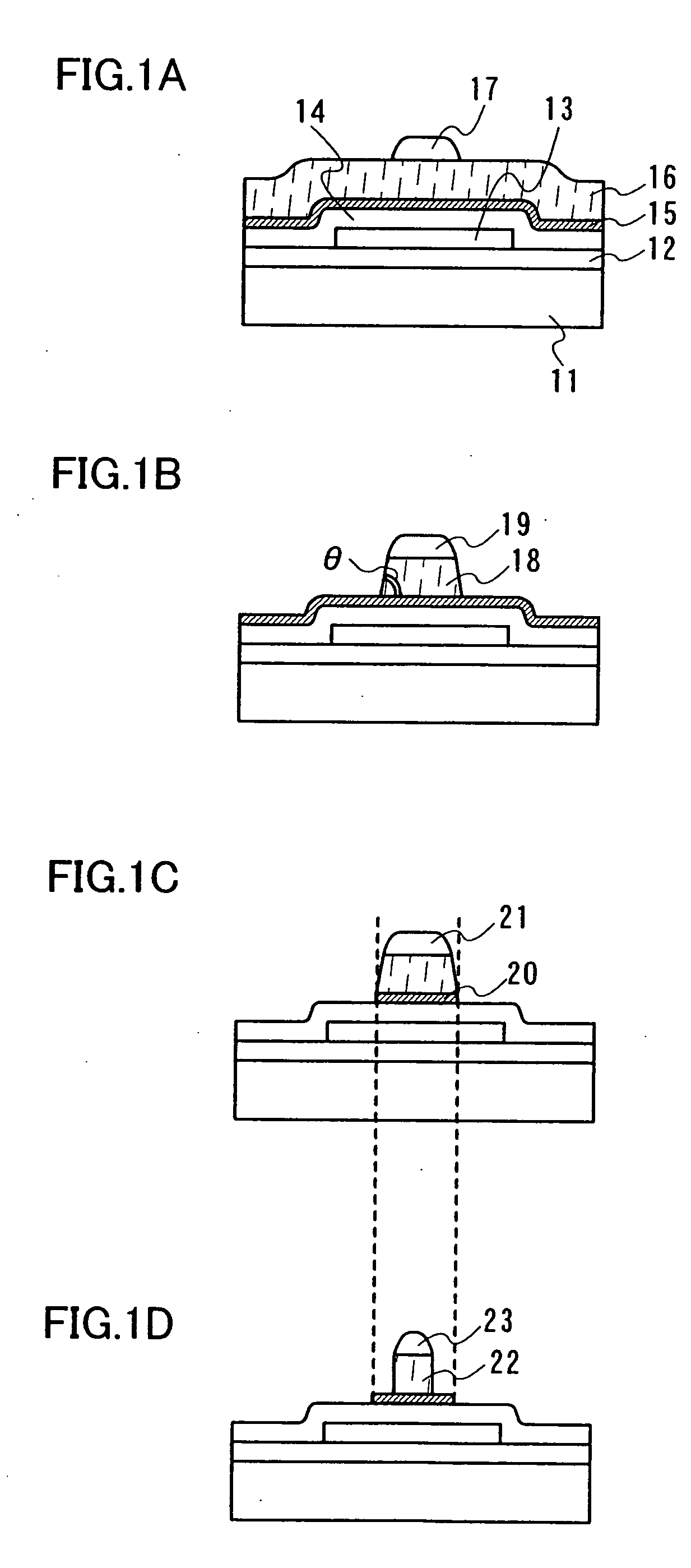
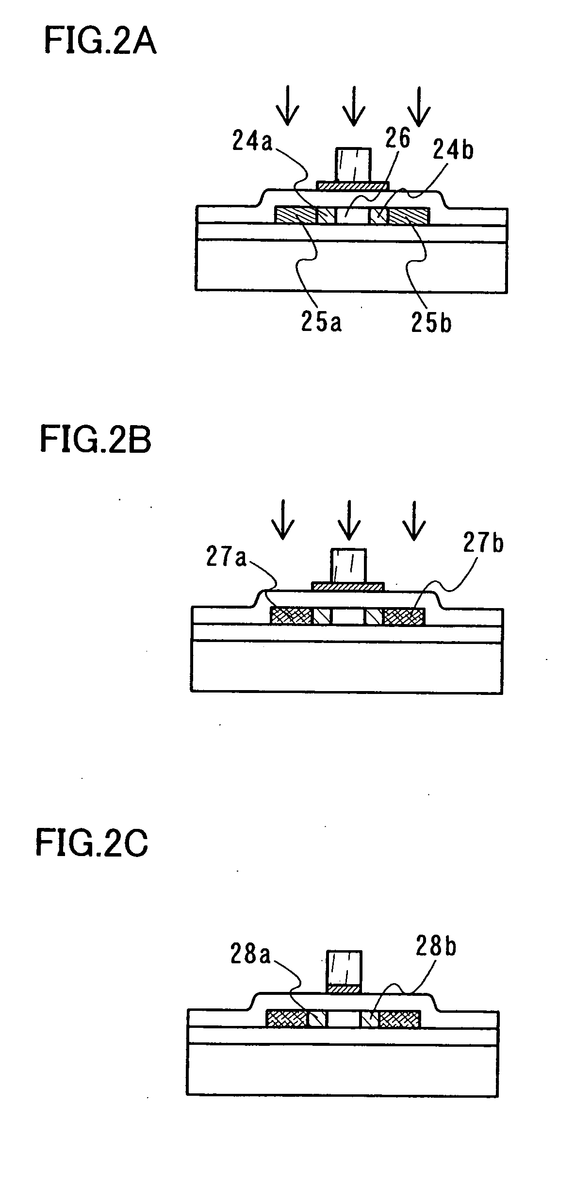
[0068] Hereinafter, a method for manufacturing a semiconductor device according to Embodiment Mode 1 is shown with reference to FIGS. 1A to 1D and FIGS. 2A to 2C. A TFT used in the semiconductor device of this embodiment mode has an LDD region of a Lov region or a Loff region.
[0069] First, a base insulating film 12 is formed over a substrate 11 in a thickness of 100 nm to 300 nm. The substrate 11 may be an insulating substrate such as a glass substrate, a quartz substrate, a plastic substrate, or a ceramic substrate; a metal substrate; a semiconductor substrate; or the like.
[0070] The base insulating film 12 can be formed using a single layer structure or a multilayer structure of an insulating film having oxygen or nitrogen such as silicon oxide (SiOx), silicone nitride (SiNx), silicon oxynitride (SiOxNy) (x>y), or silicon nitride oxide (SiNxOy) (x>y). It is preferable to form a base insulating film in particular when impurities from a substrate are concerned.
[0071] In addition,...
embodiment mode 2
[0102] This embodiment mode shows a method for manufacturing a semiconductor device having a Loff region with reference to FIGS. 3A to 3C.
[0103] In this embodiment mode, a TFT having a hat-shaped gate electrode is formed in the same steps as Embodiment Mode 1 in FIGS. 1A to 1D to obtain a state shown in FIG. 3A.
[0104] Thereafter, the island-shaped semiconductor film not overlapped with the second gate electrode 20 is partially doped with an impurity element by performing a first doping using the second and the third gate electrodes as masks (FIG. 3B). Through this doping, low-concentration impurity regions 31a and 31b and a channel-forming region 35 are formed. The doping is performed so that the concentrations of the impurity elements in the low-concentration impurity regions 31a and 31b are each 1×10¹⁶ atoms / cm3 to 1×10²⁰ atoms / cm3, preferably 1×10¹⁶ atoms / cm3 to 5×10¹⁸ atoms / cm3.
[0105] Next, a second doping for forming high-concentration impurity regions is performed (FIG. 3C)...
embodiment mode 3
[0108] This embodiment mode explains a method for manufacturing a semiconductor device having-both a Lov region and a Loff region with reference to FIGS. 4A to 4D. In this embodiment mode, a TFT having a hat-shaped gate electrode and an impurity region is formed in the same steps as Embodiment Mode 1 in FIGS. 1A to 2A (FIG. 4A).
[0109] Next, a film 41 formed from a silicon compound is formed over the gate electrode in 100 nm thick by using a known film forming method (FIG. 4B). In this embodiment mode, a silicon oxide film is used as the film 41. Then, sidewalls 42 shown in FIG. 4C are formed by etching back the film 41 formed from a silicon compound. When the difference between the gate length of the second gate electrode and that of the third gate electrode is extremely small, the sidewalls 42 are formed so that not only the side surfaces of the third gate electrode but also those of the second gate electrode are covered.
[0110] Then, a second doping is performed as shown in FIG. ...
PUM
 Abstract
Description
Claims
Application Information
 - R&D
- Intellectual Property
- Life Sciences
- Materials
- Tech Scout
- Unparalleled Data Quality
- Higher Quality Content
- 60% Fewer Hallucinations
Browse by: Latest US Patents, China's latest patents, Technical Efficacy Thesaurus, Application Domain, Technology Topic, Popular Technical Reports.
© 2025 PatSnap. All rights reserved.Legal|Privacy policy|Modern Slavery Act Transparency Statement|Sitemap|About US| Contact US: help@patsnap.com


