Model railroad system

Inactive Publication Date: 2006-05-04
LIEBMAN JOHN R +1
View PDF8 Cites 7 Cited by
  • Summary
  • Abstract
  • Description
  • Claims
  • Application Information

AI Technical Summary

Benefits of technology

[0003] The primary object of the present invention is to provide a model railroad locomotive that avoids or at least reduces the time required for cleaning of the rails and wheels. SUMMARY
[0005] The source of rechargeable power may comprise an array of rechargeable batteries carried in the locomotive itself or on another car, for example, in the case of model steam locomotives, in the locomotive tender, thereby completely avoiding any reliance on the tracks for electrical current. Remotely controlled model railroad locomotives can be operated on conventional model railroad layouts without interfering with present methods of operating model trains, thereby permitting a gradual transition from conventional power supplies to battery power without incurring large conversion expense.
[0007] A convenient means by which the radio crystals can be easily changed in the locomotive will be disclosed, allowing the simultaneous operation of several locomotives independently or of multiple locomotives together, much as they are operated in full-size railroad operations and without exceeding the capacity of the transformer.

Problems solved by technology

Dirt, oil and other contaminants readily adhere to the rails due to static electricity and significantly interfere with smooth operation of fine-scale model railroads, requiring the operators to spend a great deal of time and effort in cleaning the rails and wheels.

Method used


Image

  • Model railroad system
  • Model railroad system
  • Model railroad system

Examples


Embodiment Construction

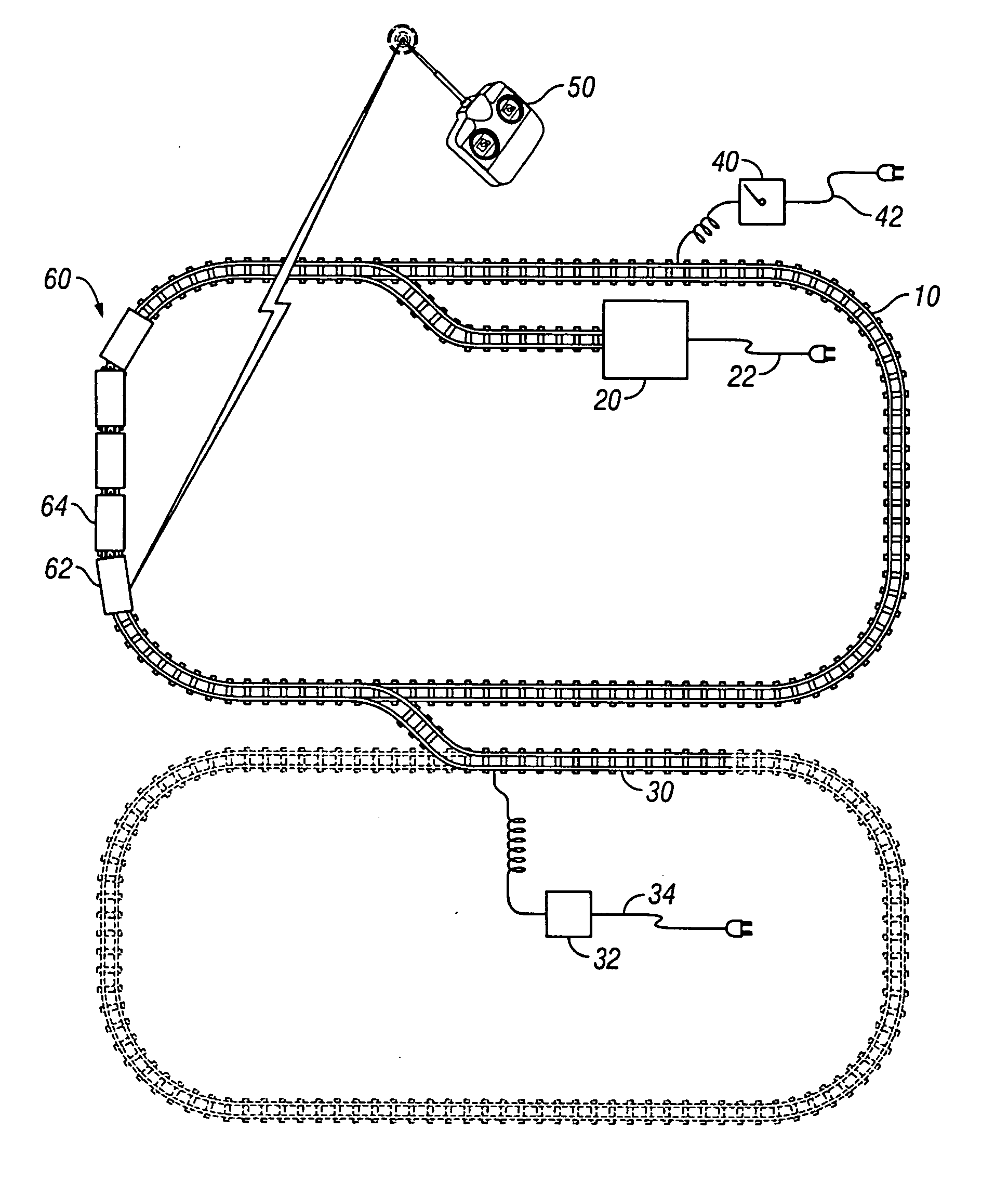
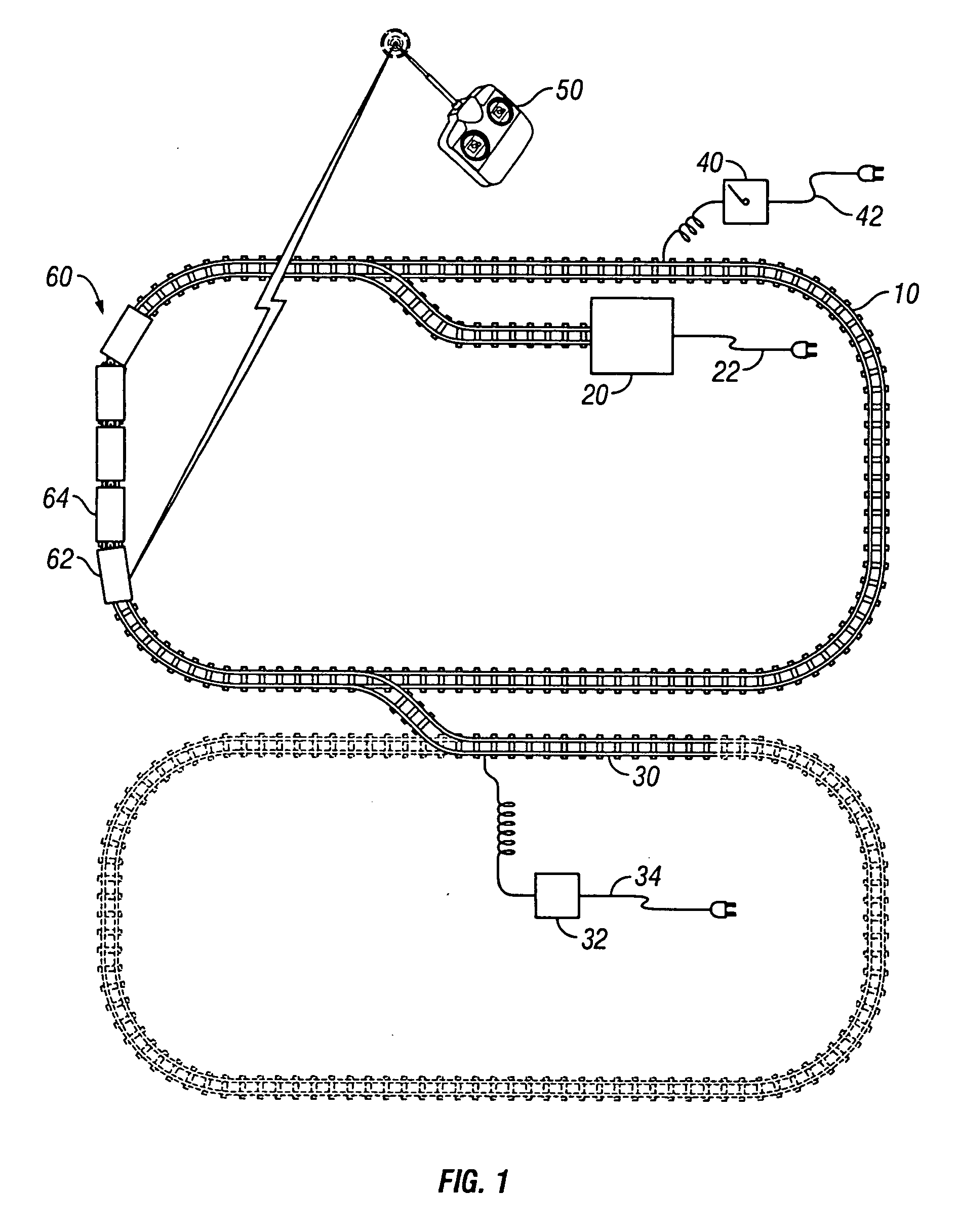
[0016]FIG. 1 schematically shows a model railroad system having a main track 10, a first charging station 20 and a second charging station 30 which comprises an electrically energizable section of track separate from the main track and a charger 32 connectable by an electric cord 34 to a conventional wall outlet. Although the main track 10 is shown in the form of a loop for simplicity, the configuration of the main track 10 can take any desired form as desired by the model railroad enthusiast. Similarly, the second charging station 30, shown in solid lines as a dead end section of track on which the locomotive can be parked for charging a rechargeable source of electrical power 80 mounted on the locomotive or on a separate car moveable with the locomotive, may also comprise a loop as shown in broken lines or any other desired configuration. Optionally, a transformer 40 which may be connected via an electrical cord 42 to a wall outlet is shown for electrically energizing the main tra...


PUM


Abstract

A model railroad system comprises a main track; a charging station; and a locomotive having an electric motor and wheels moveable along the track. A rechargeable source of electrical power is moveable with the locomotive and electrically conductive contacts on the locomotive or on a car connected to the locomotive engage electrically conductive recharging contacts at the charging station. A wirelessly controllable motor control circuit moveable with the locomotive supplies electrical power from the rechargeable source to the motor and controls the speed and direction of movement of the locomotive along said track.

Description

CROSS REFERENCE TO RELATED APPLICATIONS, IF ANY [0001] None BACKGROUND OF THE INVENTION AND PRIOR ART [0002] The present invention relates generally to model railroads and more particularly to model railroads of the type in which electrical power is ordinarily supplied from electrically conductive tracks to a locomotive. Typically, an electric motor on the locomotive transmits power to the drive wheels through a drive shaft and gear set generally mounted on or near its axles. These locomotives generally rely for power on a variable direct voltage of up to 12 volts on a two-rail system or, with a three-rail system, a variable alternating voltage of up to 18 volts. Power is supplied to the track by an electrical transformer connected to a wall outlet. The transformer includes controls to enable the operator to propel the locomotive and train at a selected speed and direction. The locomotive relies for power on the current conducted through the rails to the motor and thence to the axle...

Claims


Application Information

Patent Timeline
IPC IPC(8): B61D1/00
CPCA63H19/24A63H30/04
Inventor LIEBMAN, JOHN R.FELDMANN, JEFF
Owner LIEBMAN JOHN R
Why Eureka
Try Eureka