
Surgical instrument system

a surgical instrument and system technology, applied in the field of surgical instrument systems, can solve the problems of inability to convey the observation unit into the operating area by a separate means of access, and the use of a small cutting blade in morcellating large tissue areas requiring morcellation can last quite a long time, and achieve the effect of simple construction

Inactive Publication Date: 2006-04-27
KARL STORZ GMBH & CO KG
View PDF21 Cites 20 Cited by
  • Summary
  • Abstract
  • Description
  • Claims
  • Application Information

AI Technical Summary

Benefits of technology

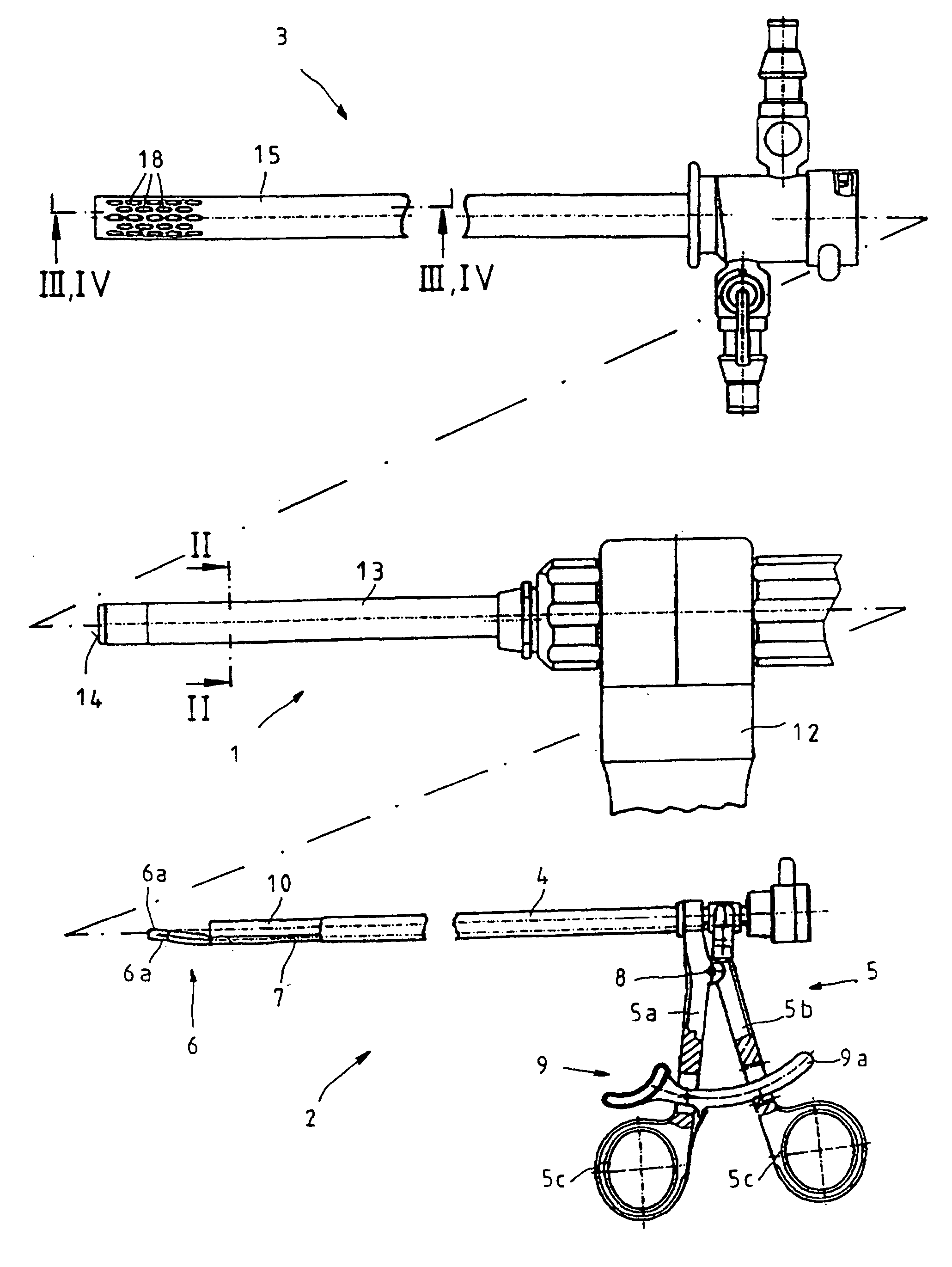
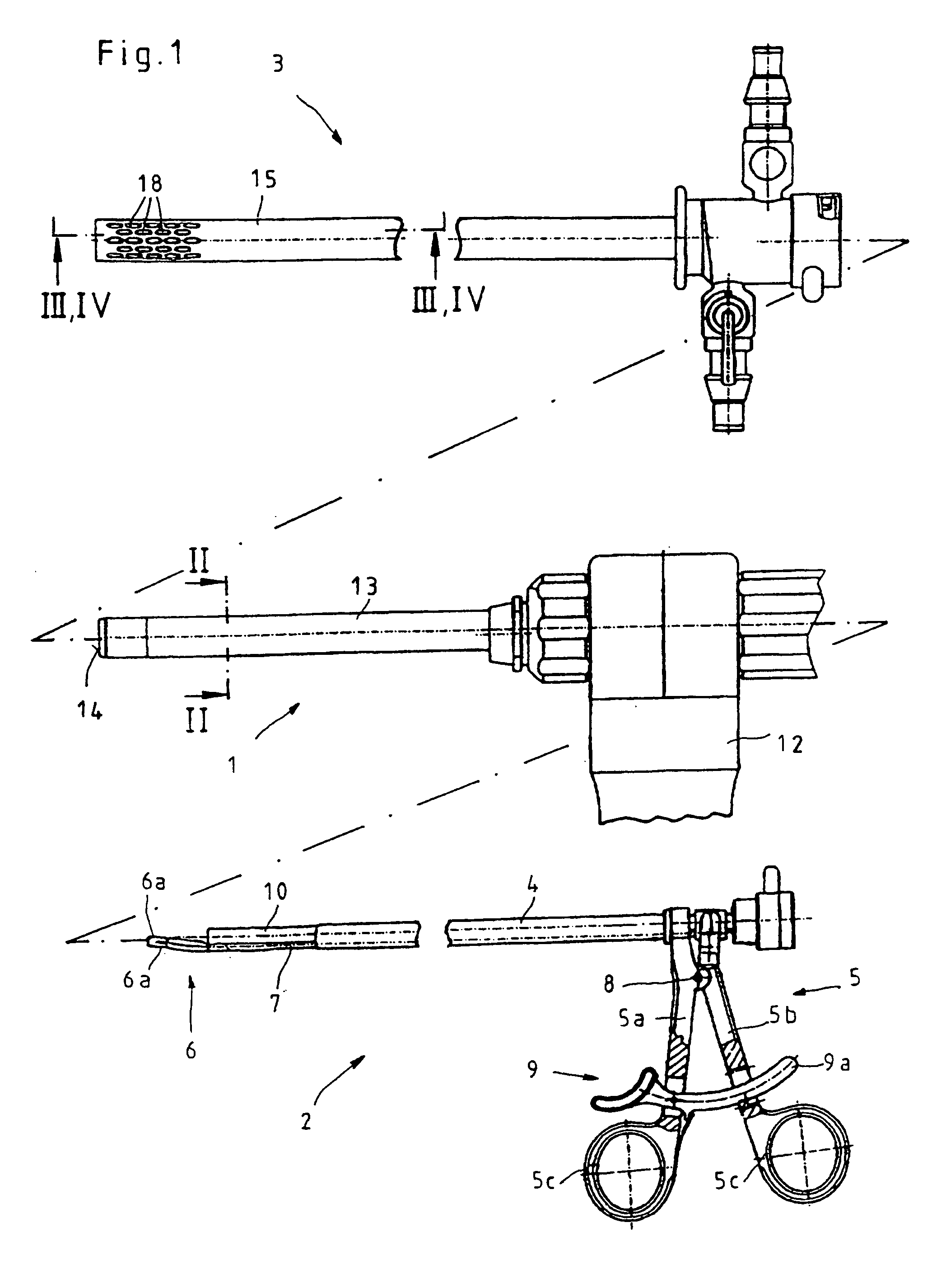
[0007] Consequently, it is the object of the invention to create a surgical instrument system that consists of a morcellator and a gripping instrument, is of simple construction, and can be used in a variety of ways.
[0010] Therefore the surgical instrument system configured in this manner is distinguished in that, thanks to the structural design of the morcellator shaft and / or of the interior of the hollow shaft of the additional medical instrument, an additional irrigation or suction canal can be configured between the shaft of the morcellator and the interior of the hollow shaft of the additional medical instrument, and this canal permits an improved use of the inventive surgical instrument system.
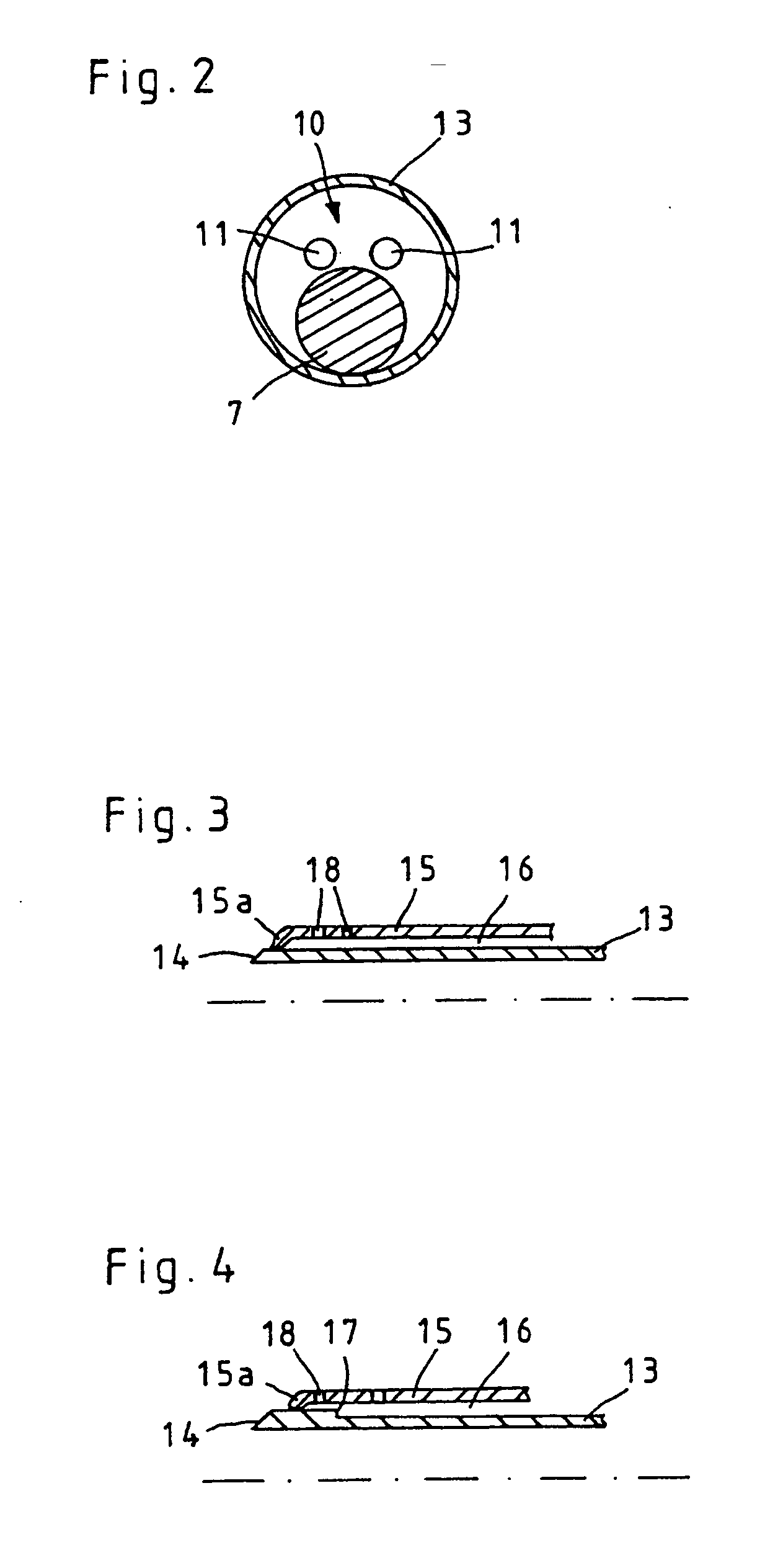
[0013] According to a third practical embodiment of the invention, the additional irrigation and / or suction canal can be configured so that the shaft of the morcellator, set off from the distal-side cutting blade, has a caliber indentation that reduces the diameter of the shaft.
[0015] It is further proposed with the invention that the gripping instrument is additionally equipped with an optical observation unit as well as at least one irrigation and / or suction canal, in such a way that the at least one irrigation and / or suction canal is positioned inside the optical observation unit. Because of the displacement of the optical observation unit and at least one irrigation and / or suction canal onto the gripping instrument and thus into the interior of the morcellator shaft, the freedom of movement of the morcellator is increased and it becomes possible to increase the morcellator diameter and thereby the cutting area.
[0016] During insertion of the morcellator into the operating area it can occur that tissue that is not to be treated comes in contact with the cutting blade of the morcellator shaft and is injured by the sharp cutting blade. Therefore, according to another embodiment of the invention, mounted on the gripping instrument is a cutting blade shield configured as a thickened area, which is adjacent at least to the cutting blade of the morcellator in form-locking connection, that is, radially flush on the inside of the shaft of the morcellator. Because of this form-locking adjacent placement on the inside of the cutting blade and the at least flush locking of the cutting blade guard with the cutting blade, injuries while inserting the morcellator are prevented.
[0019] To facilitate handling of the gripping tool for the operator, it is further proposed with the invention that the jaw members can be fixed in their relative position toward one another so that the operator, for instance, can released the gripping members of the handle without, in the process, losing the portion of tissue grasped by the jaw members.

Problems solved by technology

However, if the operating area is very limited and small, as is the case for instance in operations of the bladder, it is impossible to convey the observation unit into the operating area by a separate means of access.
It is therefore a disadvantage of this known arrangement that using a small cutting blade in morcellating large tissue areas requiring morcellation can last quite a long time.

Method used


Image

  • Surgical instrument system
  • Surgical instrument system
  • Surgical instrument system

Examples


first embodiment

[0042] In the first embodiment depicted in FIG. 3, the distal end 15a of the hollow shaft 15 of the additional medical instrument is configured arched inward to configure the additional irrigation and / or suction canal 16.

second embodiment

[0043] depicted in FIG. 4, the shaft 13 of the morcellator 1 includes, at a distance from the distal-side cutting blade 14, a caliber indentation 17 that reduces the diameter of the shaft 13 to form the additional irrigation and / or suction canal 16.

[0044] Alternatively to these two illustrated embodiments it is also possible, for instance, to configure at least one longitudinal groove in the casing surface of the shaft 13 of the morcellator 1 to form the additional irrigation and / or suction canal 16.

[0045] To allow liquid to be diverted from the operating area by means of the additional irrigation and / or suction canal 16, in the distal area of the shaft 15 of the additional medical instrument suction openings 18 are configured by means of which, for instance, blood and / or irrigation liquid can be suctioned into the additional irrigation and / or suction canal 16.

[0046] To avoid a loss of pressure through the additional irrigation and / or suction canal 16, the additional irrigation a...


PUM


Abstract

The invention relates to a surgical instrument system encompassing a morcellator with a hollow shaft on whose distal end a cutting blade is configured, as well as a gripping instrument with a shaft on whose distal end a tool consisting of at least two jaw members and on whose proximal end a handle consisting of at least two gripping members is configured to activate the tool, in such a way that the gripping instrument can be inserted into the hollow shaft of the morcellator so that it can slide in the longitudinal direction of the morcellator shaft. To ensure versatile application along with simple structure, it is proposed with the invention that the morcellator with the insertable gripping instrument can be inserted into a hollow shaft of an additional medical instrument, in particular a resectoscope, and that an additional irrigation and / or suction canal is configured between the shaft of the morcellator and the inside of the hollow shaft of the additional medical instrument.

Description

CROSS-REFERENCE TO RELATED APPLICATIONS [0001] This application is a continuation of pending International Patent Application No. PCT / EP2005 / 004196 filed on Apr. 20, 2005 designating the United States and claiming priority from German Patent Application No. 10 2004 021 713.0 filed on Apr. 30, 2004.FIELD OF THE INVENTION [0002] The invention relates to a surgical instrument system that includes a morcellator with a hollow shaft on whose distal end a cutting blade is configured as well as a gripping instrument with a shaft, having on its distal end a tool consisting of at least two jaw members and on its proximal end a handle for activating the tool consisting of at least two gripping members, in such a way that the gripping instrument can be inserted into the hollow shaft of the morcellator in the longitudinal direction of the morcellator shaft. BACKGROUND OF THE INVENTION [0003] In endoscopic surgical interventions, such as in laparoscopy, it is customary to create several points of...

Claims


Application Information

Patent Timeline
Patent Type & Authority Applications(United States)
IPC IPC(8): A61B1/00A61B1/31A61B17/28A61B17/32A61B17/34A61M1/00
CPCA61B1/015A61B1/31A61B17/29A61B17/32002A61B17/32053A61B2017/3445A61B2217/005A61B2217/007A61M1/0062A61M1/772
Inventor DOLL, FRANKWALTER, CHRISTIANROESCH, WALTER
Owner KARL STORZ GMBH & CO KG
Learn More