
Magnetic Resonance System Response Method

Inactive Publication Date: 2006-04-27
GE MEDICAL SYST GLOBAL TECH CO LLC
View PDF5 Cites 3 Cited by
  • Summary
  • Abstract
  • Description
  • Claims
  • Application Information

AI Technical Summary

Benefits of technology

[0011] One advantage of the present invention is that this method allows more accurate analysis of a system over a greater bandwidth. In addition to identifying bad or marginal components and locating spurious background noise, these response plots are processed to normalize and improve system response.
[0012] A further advantage of the present invention is increased speed and ease of use. A greater bandwidth can be analyzed automatically, thereby replacing the manually intensive and invasive task of performing the same analysis with a signal generator and a spectrum analyzer.
[0013] Still a further advantage is data mining and monitoring. System response plots may be data-mined and may become a part of a data warehouse where trends in the system response can be analyzed.

Problems solved by technology

This limit (known as the Nyquist Criterion) forms the basis of digital signal processing theory and generates a problem for completely analyzing the exciter / receiver subsystem.
This is a time consuming approach, generally only used to characterize the system when the board is first designed.
Although effective over this range, this method hinders the ability to see sufficiently beyond the passband of the filter to analyze the transition bands or the stop bands.
The disadvantages associated with current, system response analysis methods have made it apparent that a new technique for system response analysis is needed.

Method used


Image

  • Magnetic Resonance System Response Method
  • Magnetic Resonance System Response Method
  • Magnetic Resonance System Response Method

Examples


Embodiment Construction

[0023] In the following description, various operating parameters and components are described for one constructed embodiment. These specific parameters and components are included as examples and are not meant to be limiting.

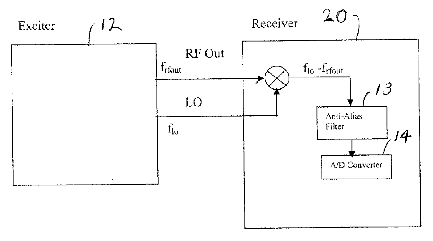
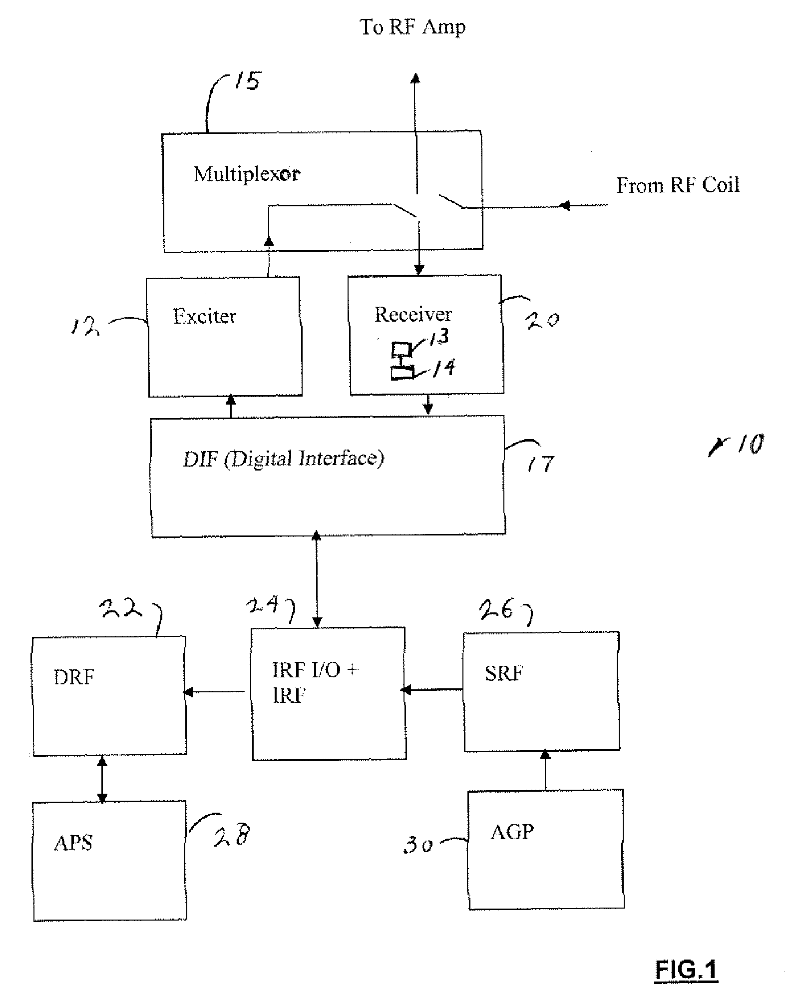
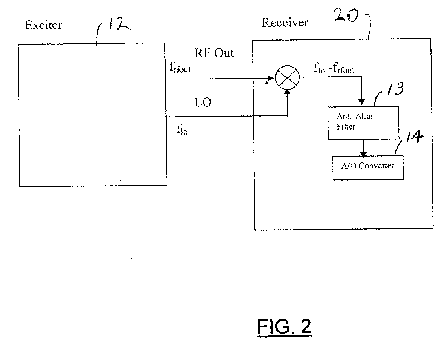
[0024] Referring now to FIG. 1, a block diagrammatic view of an exciter / receiver system 10 of a magnetic resonance (MR) system is illustrated. The system 10 includes control components, such as: an exciter 12, a receiver 20 having an anti-alias filter 13 and an analog / digital converter 14, a multiplexer 15, a Digital Interface Board (DIF) 17, a Digital Receiver Filter Board (DRF) 22, an Interface Related Function Board and input / output device (I / O) 24, a Sequencer Related Function Board (SRF) 26, a controller or Acquisition Processing System Board (APS) 28, and a secondary central processing unit under control of the APS or Application Gateway Processor Board (AGP) 30. The system 10 also includes any other MR scanner component known in the art.

[0025] Referrin...


PUM


Abstract

An imaging system includes an exciter generating a series of radio frequency pulses for dividing a frequency band having a sampled band defined by an upper folding frequency and a lower folding frequency. The system also includes a receiver receiving and digitizing the radio frequency pulse after the radio frequency pulse has been reflected. The receiver also samples the frequency band, receives a folded radio frequency pulse appearing within the sampled band, and generates therefrom a receiver signal.

Description

TECHNICAL FIELD [0001] The present invention relates generally to Magnetic Resonance (MR) systems and more particularly to a self-contained, automated method for determining a system signal response using digital sampling and alias unwrapping. [0002] Imaging devices, such as magnetic resonance (MR) scanners, are widely used in both medical and industrial applications. [0003] An MR scanner is both an analog signal generator and a digital acquisition system. During normal operation, the MR scanner generates a modulated radio-frequency (RF) output signal, which is used to excite an object in a magnet bore (e.g. a phantom or a patient). The object absorbs and reflects this output signal. This reflected output signal or echo is received and digitized in an MR computer and utilized to reconstruct an image of the object. [0004] Within the scanner, the exciter generates the output signal, and the receiver receives and digitizes the reflected output signal. For testing and diagnosis, the exc...

Claims


Application Information

Patent Timeline
IPC IPC(8): G01V3/00
CPCG01R33/3607G01R33/3621G01R33/56545
Inventor KREGAR, KEVIN SCOTTCHIANESE, JOSEPH JAMESWRIGHT, TOM
Owner GE MEDICAL SYST GLOBAL TECH CO LLC
Learn More