
Method and apparatus of making highly repetitive micro-pattern using laser writer

a laser writer and micro-pattern technology, which is applied in the direction of photomechanical equipment, instruments, material analysis through optical means, etc., can solve the problems of degrading performance, affecting the quality of laser writing,

Inactive Publication Date: 2006-04-27
PANASONIC CORP
View PDF7 Cites 94 Cited by
  • Summary
  • Abstract
  • Description
  • Claims
  • Application Information

AI Technical Summary

Benefits of technology

[0007] In accordance with the present invention, an apparatus for making a highly repetitive micro-pattern using a laser writer includes one or more diffractive optical elements. At least one diffractive optical element is adapted to split a beam of a laser writer into sub-beams based on a separation distance matching a period of a repetitive structure to be formed in a laser-writable substrate. One or more f-theta lenses are also included. At least one f-theta lens is disposed to intercept the sub-beams, forming a periodic distribution of laser writer output beams.

Problems solved by technology

This process is very slow, and the need remains for a way to improve the processing speed.
Since grating (or DOE) performance (efficiency) depends on the beam coverage over multiple periodic structures, any variation from period to period degrades the performance.
As a result, current laser writing processes are susceptible to long-term drift of parameters such as laser beam intensity, beam pointing, scanner response, scanning non-linearity and thermal expansion.
When multiple gratings (or DOES) are fabricated, variation from device to device degrades the yield and tolerance.
As a result, current laser writing processes are susceptible to long-term drift of parameters such as laser beam intensity, beam pointing, scanner response, scanning non-linearity and thermal expansion.
However, this process requires expensive equipment, leading to cost increase of the end product optics.
In the case where the optics are no longer binary structures, e.g., binary gratings, a special grayscale photo mask must be installed in a mask aligner or a stepper, which is also expensive to obtain.
However, in this method, individual elements are fabricated literally one by one, which greatly increases fabrication cost of the element even during mass production of the element.

Method used


Image

  • Method and apparatus of making highly repetitive micro-pattern using laser writer
  • Method and apparatus of making highly repetitive micro-pattern using laser writer
  • Method and apparatus of making highly repetitive micro-pattern using laser writer

Examples


first embodiment

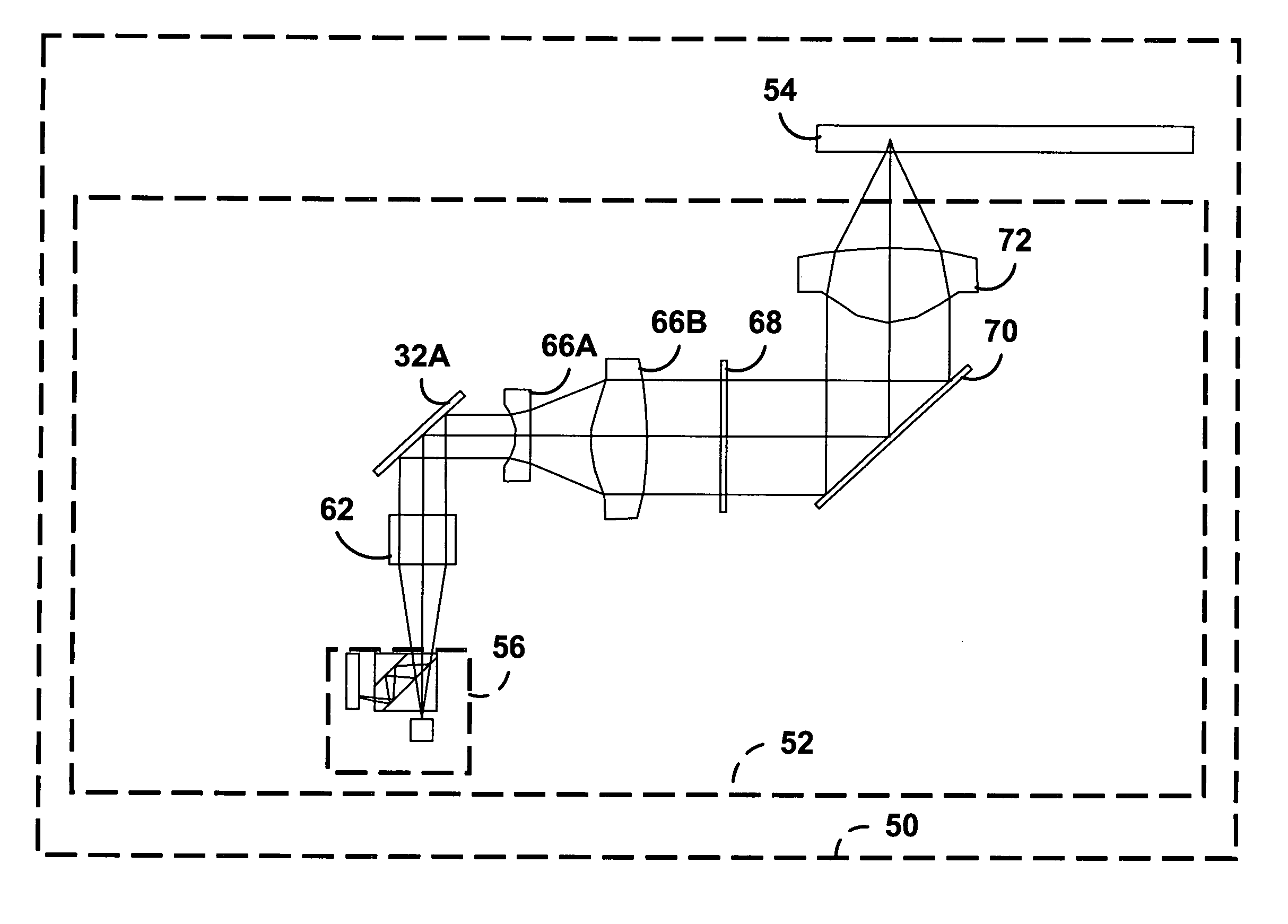
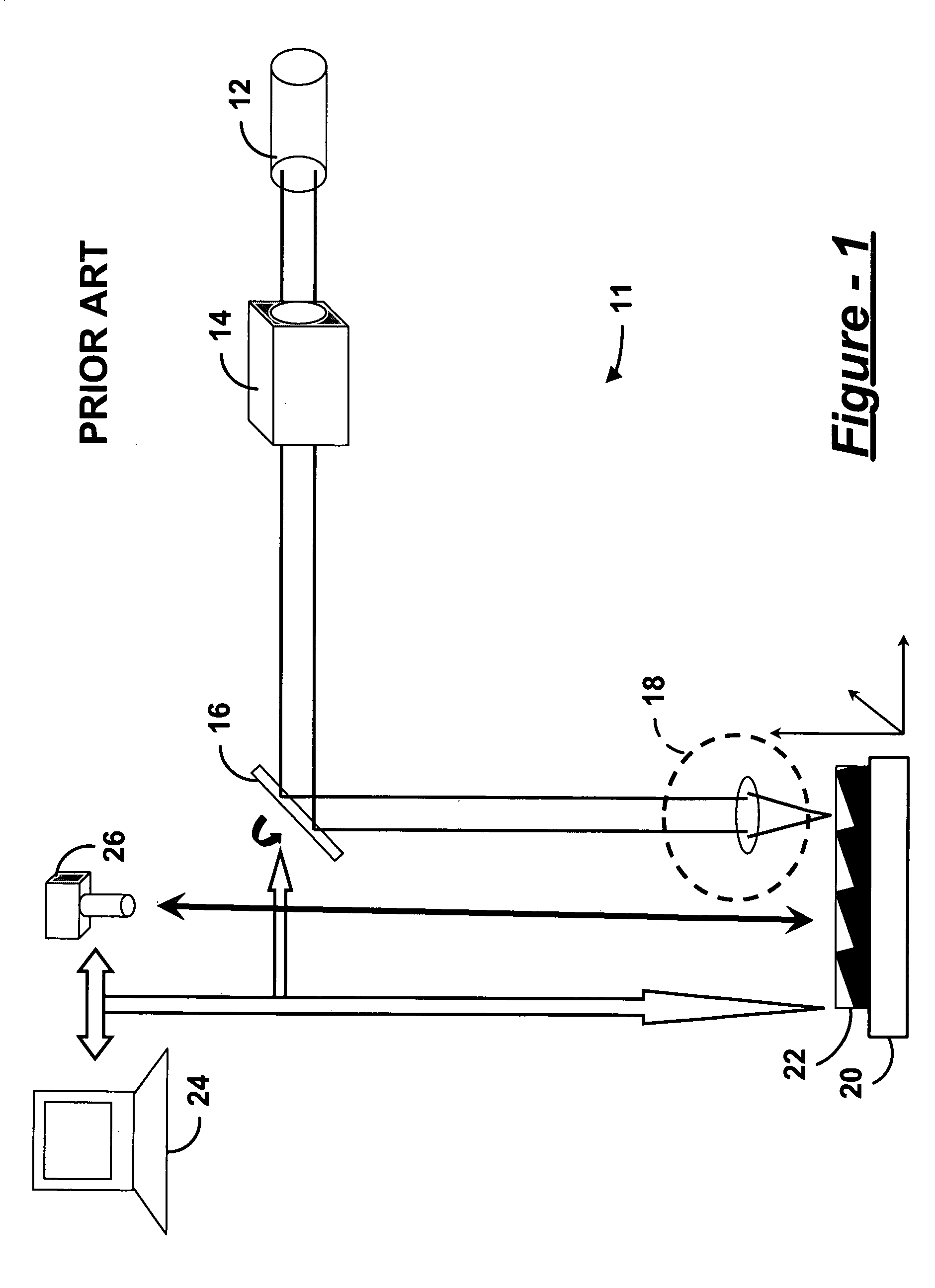
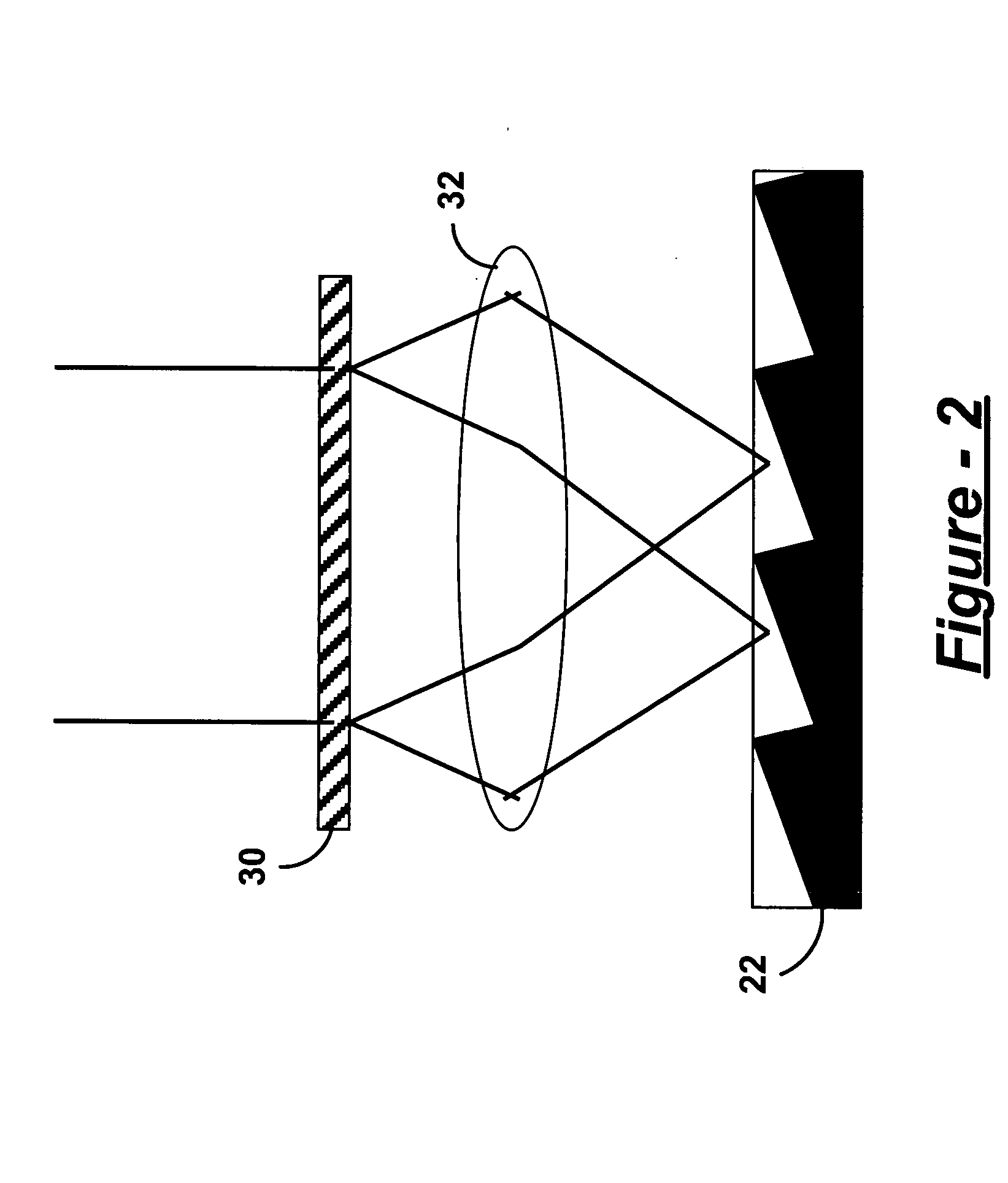
[0019] In accordance with the present invention, the laser source 12 is replaced with a high power and / or ultra-fast laser source. Also in accordance with the present invention, focal lens 18 is replaced with an apparatus according to the present invention that includes at least one DOE and having an f-theta lens as illustrated in FIG. 2. The DOE 30 is adapted to split a beam of a laser writer into sub-beams based on a separation distance matching a period of a repetitive structure to be formed in a laser-writable substrate 22. F-theta lens 32 is disposed to intercept the sub-beams and form a periodic distribution of laser writer output beams. Thus, a micro-pattern for a single structure can result in simultaneous exposure of the substrate to multiple repetitions of the micro-pattern in a highly precise manner. While two sub-beams are illustrated, it is possible to form approximately four-hundred sub-beams from a single DOE. Thus, an optical element or other micro-element having hig...

second embodiment

[0020] Turning now to FIG. 3, in a second embodiment, a first DOE 34 can be designed to split the beam to slightly larger than the spacing of each element to allow for dicing / separation. This hierarchical approach allows for parallel processing of multiple elements on a single wafer / substrate 22. For this application, the beam pattern is matched to a desired arrangement, but the arrangement of elements need not be regular. Similarly, if one DOE is not sufficient to provide coverage of the whole useable wafer area, one can first split the main laser beam into multiple separate beams as needed, and direct each beam to a separate, identical DOE for further beam splitting so as increase the covered area.

[0021] In some embodiments, the first DOE 34 produces multiple sub-beams that are intercepted by an additional f-theta scan lens 36. Then, multiple collimating lenses 38A-38D reform the sub-beams for use with multiple instances of the first embodiment. Accordingly, second DOEs 30A-30D op...


PUM


Abstract

An apparatus for making a highly repetitive micro-pattern using a laser writer includes one or more diffractive optical elements. At least one diffractive optical element is adapted to split a beam of a laser writer into sub-beams based on a separation distance matching a period of a repetitive structure to be formed in a laser-writable substrate. One or more f-theta lenses are also included. At least one f-theta lens is disposed to intercept the sub-beams, forming a periodic distribution of laser writer output beams.

Description

FIELD OF THE INVENTION [0001] The present invention generally relates to a method of and apparatus for micro-patterning a laser writable substrate using a laser writer, and particularly relates to design and use of one or more diffractive optical elements to accomplish parallel processing in a laser writer. BACKGROUND OF THE INVENTION [0002] Today's diffraction gratings, diffractive optical elements (DOEs) and / or amplitude masks for micro-devices can be obtained by using a laser writer to process a laser-writable substrate one pixel at a time. Accordingly, a single laser beam is being used to write a pattern on a whole wafer one repetitive pattern at a time. This process is very slow, and the need remains for a way to improve the processing speed. [0003] Since grating (or DOE) performance (efficiency) depends on the beam coverage over multiple periodic structures, any variation from period to period degrades the performance. As a result, current laser writing processes are susceptib...

Claims


Application Information

Patent Timeline
Patent Type & Authority Applications(United States)
IPC IPC(8): H01J3/14
CPCG03F7/70275G03F7/70316G03F7/70383
Inventor CHENG, CHEN-HSIUNGNYDICK, IRAMIZUYAMA, YOSUKE
Owner PANASONIC CORP
Learn More