
Image signal output device, coded image signal generation method, image signal output program, camera operation system, camera operation program, matrix code decoding device, and matrix code decoding program

a coded image and output device technology, applied in the field of image signal output device, coded image signal generation method, image signal output program, matrix code decoding device, etc., can solve the problem of consuming space for qr code displayed as a part of an image, and achieve the effect of effectively capturing the matrix cod

Inactive Publication Date: 2006-04-27
DENSO CORP
View PDF6 Cites 108 Cited by
  • Summary
  • Abstract
  • Description
  • Claims
  • Application Information

AI Technical Summary

Benefits of technology

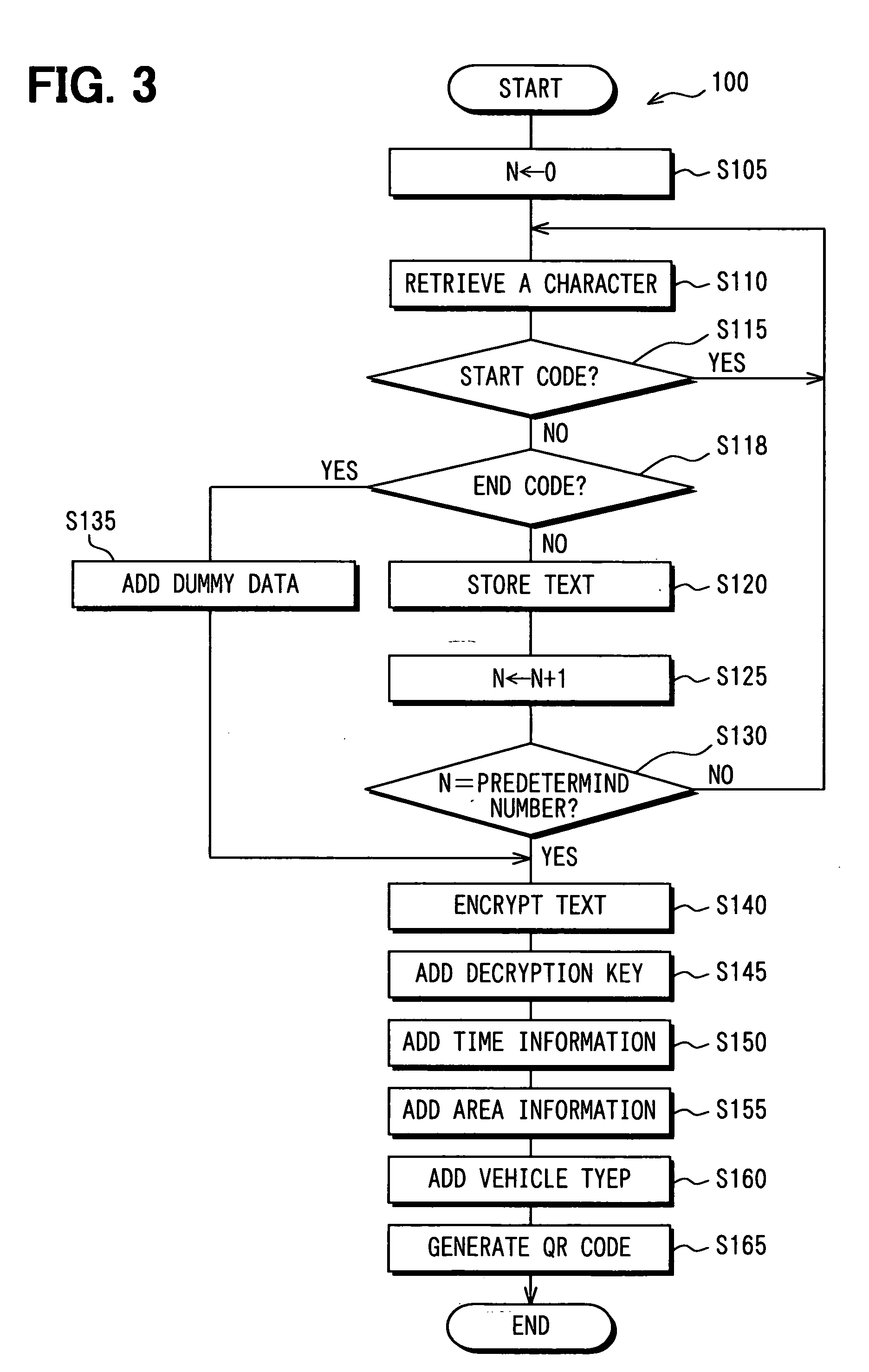
[0017] The matrix code generated from an encrypted source data may include the decryption key. In this manner, the recipient of the matrix code can easily decrypt the encrypted source data in the matrix code.
[0022] The matrix code decoding system may determine a start data and an end data for defining a block of data. That is, the decoding system continuously captures the matrix codes in the images, and the start data and the end data are collected based on the difference of the captured images. In this manner, the matrix code decoding system treats data between the start data and the end data as an integrated body of data, thereby enabling the conveyance of a greater amount of data that cannot be conveyed by using a single image of the matrix code.
[0023] The camera in the decoding system may be synchronized with the display of the matrix code for effectively capturing the matrix code.

Problems solved by technology

However, the QR code displayed as a part of an image consumes a space for displaying other information and / or images on the display.

Method used


Image

  • Image signal output device, coded image signal generation method, image signal output program, camera operation system, camera operation program, matrix code decoding device, and matrix code decoding program
  • Image signal output device, coded image signal generation method, image signal output program, camera operation system, camera operation program, matrix code decoding device, and matrix code decoding program
  • Image signal output device, coded image signal generation method, image signal output program, camera operation system, camera operation program, matrix code decoding device, and matrix code decoding program

Examples


Embodiment Construction

[0040] An embodiment of the present invention is described with reference to the drawings.

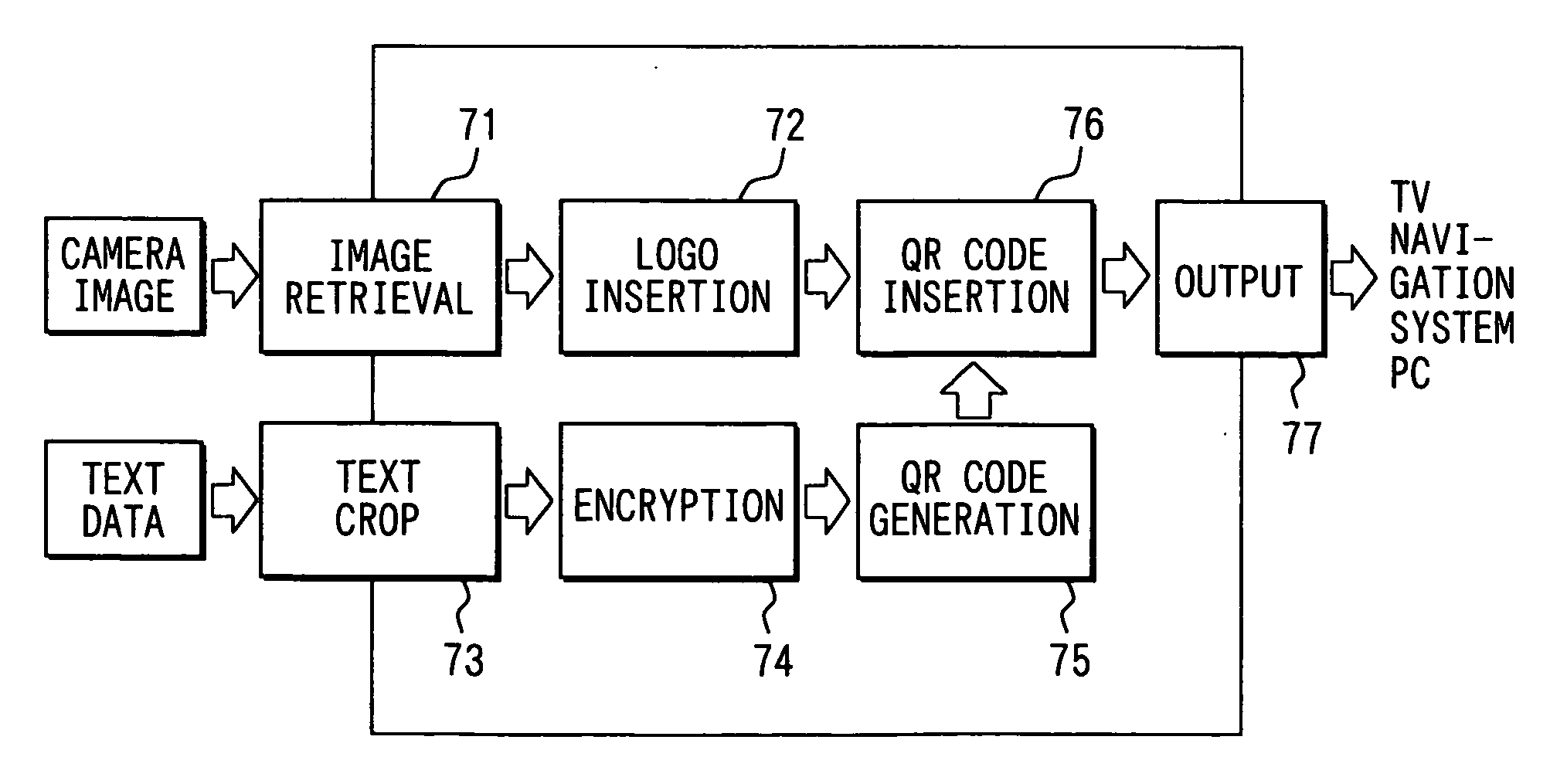
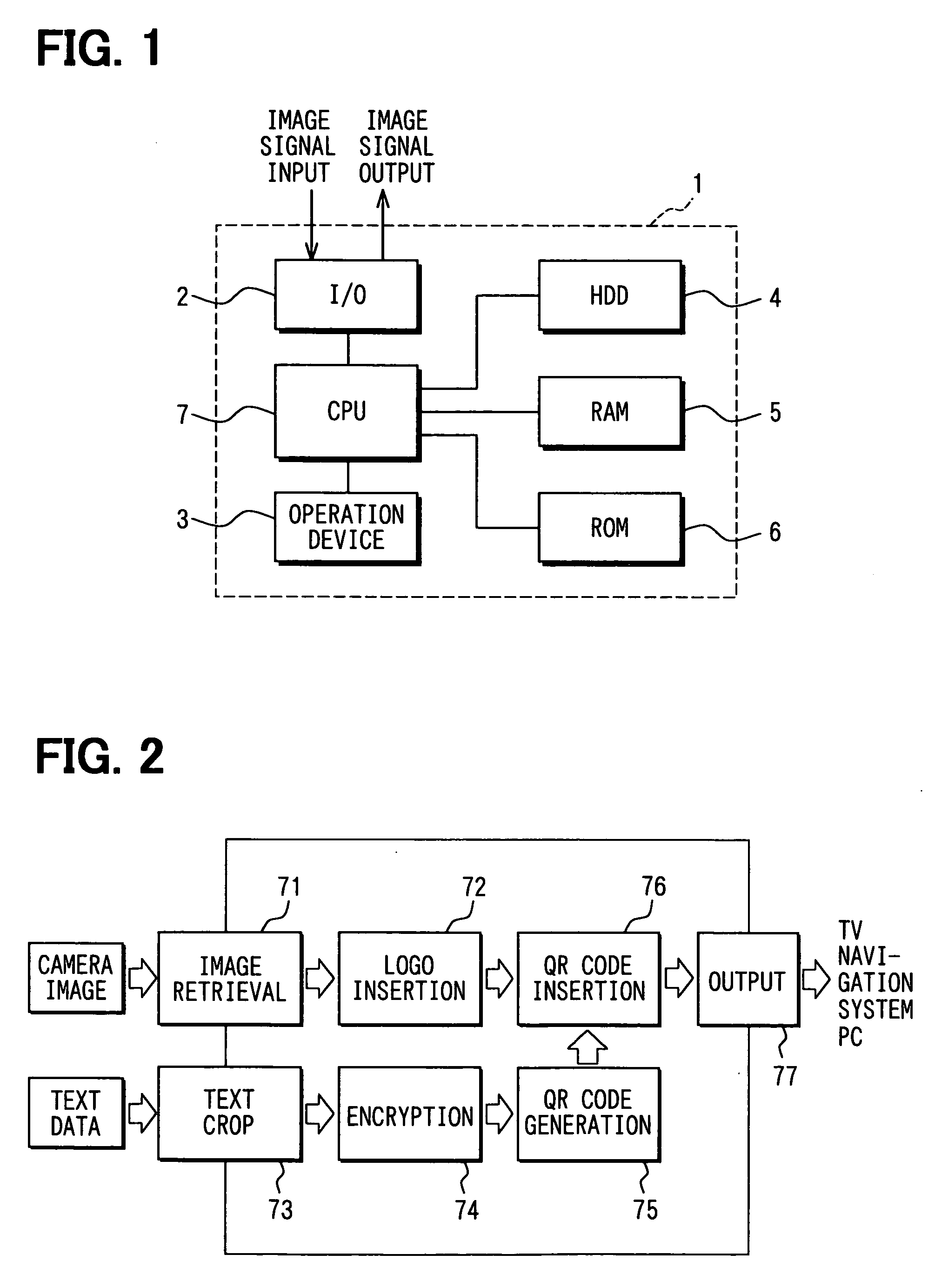
[0041]FIG. 1 shows a block diagram of an image signal output device 1 in an embodiment of the present invention. The image signal output device 1 includes an input / output (I / O) interface 2, an operation device 3, a hard disk drive (HDD) 4, a random access memory (RAM) 5, a read only memory (ROM) 6, and a central processing unit (CPU) 7. The image signal output device 1 generates a QR code (Registered trademark) from source data such as text data or the like, and outputs a primary image generated from an image signal with an imperceptible QR code inserted therein to a recipient.

[0042] The I / O interface 2 receives input of image signal from external devices such as a camera or the like, and outputs the image signal as digital data to CPU 7. The I / O interface 2 also receives input of image signal as digital data from the CPU 7, and outputs the image signal as digital or analog data to the extern...


PUM


Abstract

An image signal output device includes a code generating means for generating a two-dimensional geometrical code based on a source data, a obtaining means for retrieving a sequential image signal, a code inserting means for inserting the two-dimensional geometrical code in the sequential image signal and a output means for outputting the sequential image signal. The code inserting means imperceptibly inserts the two-dimensional geometrical code in the sequential image signal, and the output means outputs the sequential image signal having the two-dimensional geometrical code inserted therein. The imperceptible two-dimensional geometrical code is captured by a camera in a cell phone to be decoded and stored in a memory medium.

Description

CROSS REFERENCE TO RELATED APPLICATION [0001] This application is based on and claims the benefit of priority of Japanese Patent Application No. 2004-312409 filed on Oct. 27, 2004, the disclosure of which is incorporated herein by reference. FIELD OF THE INVENTION [0002] The present invention generally relates to a device for inputting and outputting an image signal with matrix codes embedded therein, a program for operating the device, and a method for generating the image signal with the matrix code. The present invention also relates to a matrix code decoding device and a decoding program used therein. BACKGROUND OF THE INVENTION [0003] In recent years, a matrix code, i.e., a two dimensional bar code, such as QR code (Registered trademark) or similar type of coding method that uses geometrical patterns, is used to convey information as a printed pattern of black and white image on a poster, a brochure or the like. That is, a recipient of the information captures the printed patte...

Claims


Application Information

Patent Timeline
Patent Type & Authority Applications(United States)
IPC IPC(8): G06K7/10G06T1/00H04N1/387H04N1/40H04N5/91
CPCG06K7/10712G06K7/1095
Inventor ONOGI, NOBUYOSHI
Owner DENSO CORP
Learn More