Dielectric-resonator array antenna system

a technology of dielectric resonance and array antennas, applied in the direction of antennas, radiating element structural forms, antenna adaptation in movable bodies, etc., can solve the problems of increasing air drag and more weight of the aircraft on which the antenna system is mounted, reducing the flying range of the aircraft, and increasing fuel consumption

Inactive Publication Date: 2006-04-20
STRICKLAND PETER C
View PDF0 Cites 227 Cited by
  • Summary
  • Abstract
  • Description
  • Claims
  • Application Information

AI Technical Summary

Problems solved by technology

Aeronautical antenna systems for satellite communications can be very large in area, which results in increased air drag and more weight for the aircraft on which the antenna system is mounted.
Increased drag and weight result in a reduction in the aircraft's flying range, increased fuel consumption and corresponding higher aircraft operational costs.
Large antenna systems can also increase lightning and bird strike risks, as well as degrade the visual aesthetics of the aircraft.
The crossed-dipole element is relatively tall, resulting in high drag, and the microstrip patch element has both narrow beamwidth and narrow bandwidth, which restrict the antenna's performance.
The narrow beamwidth of the patch element results in excessive gain loss and impedance mismatch when the array beam peak is scanned toward the aircraft horizon with the antenna mounted on the top of the fuselage.
The narrow bandwidth of the patch radiator makes the impedance mismatch more catastrophic at extreme scan angles.
These effects reduce the gain of the antenna system, thus demanding a larger antenna footprint and overall larger antenna size.
This approach does not minimize interference with other satellites on the geosynchronous arc and consequently the size of the conventional antenna must be relatively large in order to achieve a desired degree of isolation against adjacent satellites.
The Omnipless HGA 7000 antenna system has not yet been sold commercially and is of unknown construction.
Further, the mounting of a phase-scanned array to an aircraft can be problematic if the goal is to minimize size and drag.

Method used


Image

  • Dielectric-resonator array antenna system
  • Dielectric-resonator array antenna system
  • Dielectric-resonator array antenna system

Examples


Embodiment Construction

[0029] It is to be understood that the figures and descriptions of the present invention have been simplified to illustrate elements that are relevant for a clear understanding of the present invention, while eliminating, for the purpose of clarity, many other elements found in typical antenna applications, and systems and methods of using the same. Those of ordinary skill in the art may recognize that other elements and / or steps are desirable and / or required in implementing the present invention. However, because such elements and steps are well known in the art, and because they do not facilitate a better understanding of the present invention, a discussion of such elements and steps is not provided herein. The disclosure herein is directed to all such variations and modifications to such elements and methods known to those skilled in the art.

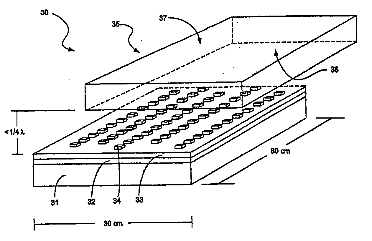
[0030] The dielectric resonator element array (DRA) antenna system of the invention is well suited for use in a wide range of applications,...


PUM


Abstract

A dielectric resonator element array (DRA) antenna system and method for using same is disclosed. The dielectric resonator antenna system includes a ground plain, a feed structure, an array of dielectric resonator elements electrically coupled to the feed structure, each dielectric element having a relatively high permittivity, a radome close to or in contact with the array of dielectric resonator elements, an object mounting apparatus for mounting the antenna system on an object, and a beam shaping and steering controller, the beam shaping and steering controller controlling the feed structure to thereby control excitation phases of the dielectric resonator elements.

Description

CROSS-REFERENCE TO RELATED APPLICATIONS [0001] This application claims priority to U.S. patent application Ser. No. 10 / 858,262, entitled “Dielectric-Resonator Array Antenna System” filed Jun. 1, 2004, which application is hereby incorporated by reference herein as if set forth in the entirety.FIELD OF THE INVENTION [0002] This invention relates generally to antennae, and, more particularly, to dielectric-resonator array antennae system and method. BACKGROUND OF THE INVENTION [0003] Aeronautical antenna systems for satellite communications can be very large in area, which results in increased air drag and more weight for the aircraft on which the antenna system is mounted. Increased drag and weight result in a reduction in the aircraft's flying range, increased fuel consumption and corresponding higher aircraft operational costs. Large antenna systems can also increase lightning and bird strike risks, as well as degrade the visual aesthetics of the aircraft. [0004] Communications wit...

Claims


Application Information

Patent Timeline
Patent Type & Authority Applications(United States)
IPC IPC(8): H01Q9/04H01Q1/28H01Q1/38H01Q21/06
CPCH01Q1/288H01Q9/0485H01Q21/064
Inventor STRICKLAND, PETER C.
Owner STRICKLAND PETER C
Why Eureka
Try Eureka