
Rentricity Flow-to-Wire and RenFlow information services

a technology of information services and renflow, which is applied in the direction of mechanical energy handling, mechanical equipment, machines/engines, etc., can solve the problems of not performing useful work with the energy they remove from the system, the pressure reduction valves lowering the pressure to optimal levels without performing useful work with the energy, etc., to facilitate information services, maximize power production and efficiency, and enable overall piping optimization

Inactive Publication Date: 2006-04-20
SCHARFSPITZ JASON SYLVAIN +1
View PDF11 Cites 12 Cited by
  • Summary
  • Abstract
  • Description
  • Claims
  • Application Information

AI Technical Summary

Benefits of technology

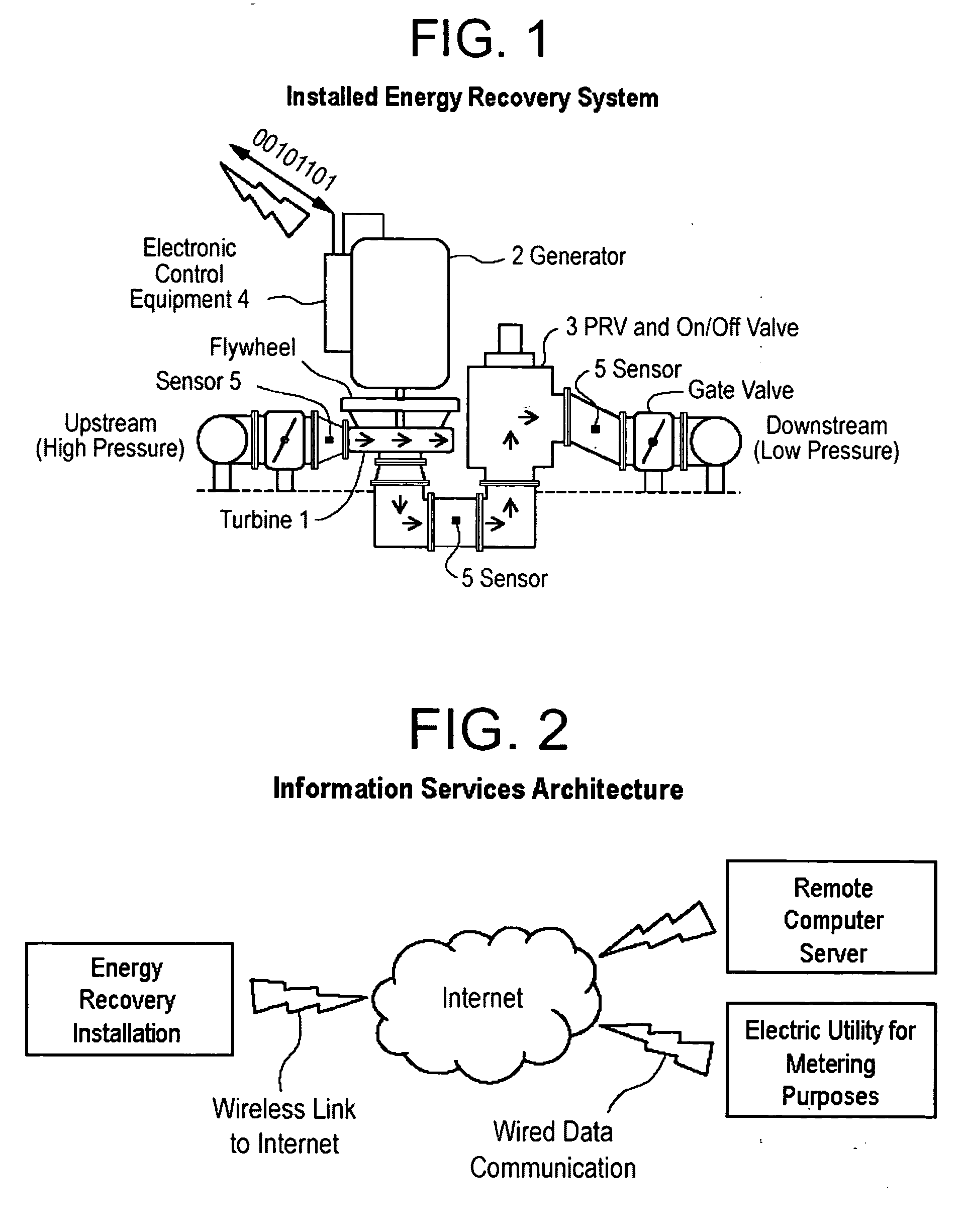
[0013] The invention includes information services that will monitor and deliver valuable operating information. The information services will be facilitated by software and hardware that stores data and makes it available in a variety of useful formats over wired and wireless networks. The information services will be accessed via the Internet and rely primarily on server-side software that contains application logic. The invention provides a method of systematically accumulating data from remote power generation sites, performing analytics on the information, and making it available in a variety of formats to maximize power production and efficiency and to enable overall piping optimization.
[0014] The invention will not produce any air pollution or waste ash—byproducts of fossil fuel electricity generation plants—nor further the environmental impact that occurs during the extraction of coal, natural gas, and oil. The invention, similar to other existing renewable technologies, will help to lessen dependence on oil and coal for energy. The invention provides a method for applying energy recovery system revenue to the costs of monitoring and securing infrastructure with minimal impact on rates to customers.

Problems solved by technology

Presently, pressure reduction valves lower pressure to optimal levels without performing useful work with the energy they remove from a system.
Pressure reduction valves have been used for decades to lower the pressure of piped materials to optimal levels—and have not performed useful work with the energy they remove from the system.

Method used


Image

  • Rentricity Flow-to-Wire and RenFlow information services
  • Rentricity Flow-to-Wire and RenFlow information services

Examples


Embodiment Construction

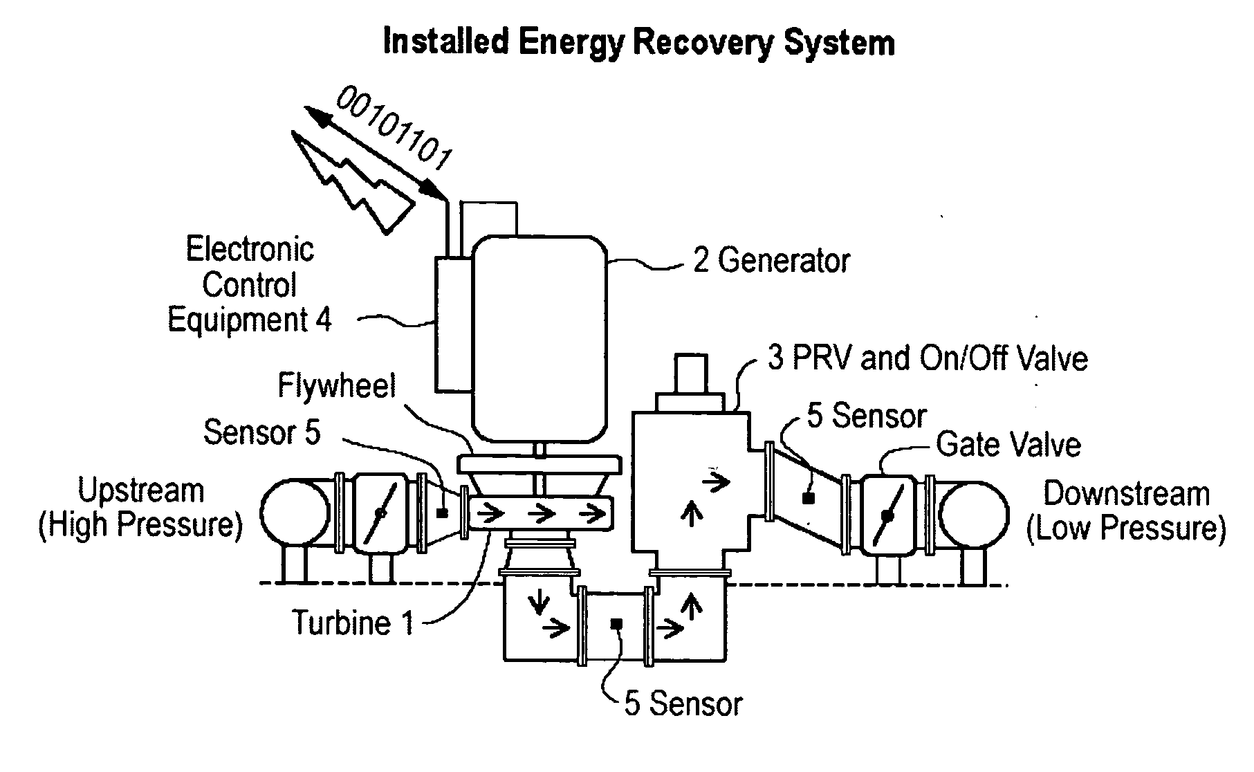
[0017] Energy Recovery System Method—The invention's micro-turbine will operate autonomously and consist of a number of components that together comprise a complete energy recovery system. The primary components are listed below and are illustrated in FIG. 1.

[0018] Turbine (1) Flowing material will spin the turbine and coupled generator. The turbine will remove the surplus energy from the material by offering a level of resistance, similar to the resistance provided by a valve. The invention usually will use Francis or reverse-pump designs during early installations. During later installations, the invention will include use self-configuring turbines in its systems. The self-configuring models automatically will modify their shape to maintain optimal efficiency across a range of flow and pressure conditions. A connected flywheel will develop momentum and inertia to resist rapid fluctuations in the flow of material through the energy recovery system and to closely maintain consisten...


PUM


Abstract

The invention is focused on transforming untapped energy in man-made processes into electricity. The surplus power being targeted is contained within pipes where gases, liquids, or solids exert extra pressure. This can be a byproduct of a chemical reaction, occur during release of compressed gas, or result from gravity pulling material from an elevated physical position to a lower one. To harness this energy the invention consists of a micro-turbine, generator, sensors, processors, electronic controls, and communications equipment that operate autonomously. The electricity produced by the devices will be consumed by a generating entity, delivered to other end-users, or sold into the power grid. The invention will use information services, comprised of computer software, to acquire, store, and report performance and security information transmitted from remote locations to persons who work for the generating entity and / or other third parties.

Description

FIELD OF INVENTION [0001] This invention relates to processes for the recovery of energy from man-made systems by extracting lost energy from pressurized flows. More particularly, this invention provides energy recovery while monitoring the related infrastructure. BACKGROUND [0002] Renewable energy sources are in demand to offset reliance on traditional forms of power generation. [0003] Surplus power is contained within pipes where gases, liquids, or solids exert extra pressure. This can be a byproduct of a chemical reaction, occur during release of compressed gas, or result from gravity pulling material from an elevated physical position to a lower one. [0004] Presently, pressure reduction valves lower pressure to optimal levels without performing useful work with the energy they remove from a system. For example, in municipal water distribution—specifically where water is stored at high elevation relative to the population it serves. Tall water columns create excessive pressure at...

Claims


Application Information

Patent Timeline
IPC IPC(8): H02K7/18F03G7/08F02B63/04
CPCF03D11/00F03G3/00F03G3/08F05B2220/602F05B2250/82Y02E10/722F03D80/00Y02E10/72F03G3/096
Inventor SCHARFSPITZ, JASON SYLVAINZAMMATARO, FRANK VINCENT
Owner SCHARFSPITZ JASON SYLVAIN
Learn More