Cytological imaging systems and methods

Inactive Publication Date: 2006-04-13
CYTYC CORP
View PDF99 Cites 18 Cited by
  • Summary
  • Abstract
  • Description
  • Claims
  • Application Information

AI Technical Summary

Benefits of technology

[0032] According to an aspect of the invention, the automatic focusing and imaging of locations of specimens on sample slides allows thorough analysis of sample slides, such as biological or cytological sample slides, at accuracies and speeds much greater than would otherwise be possible. During the analysis of a slide, it is routinely necessary to readjust focus at various locations on the slide. Systems that are designed to automatically image substantially all of a region of interest of a slide need to enable the automatic adjustment of focus for various locations within that region of interest. A system which runs through a complete autofocusing procedure at every position it images may accurately image substantially all of a region of interest, but it is inefficient, since many of the autofocusing steps taken have been determined to be redundant and therefore unnecessary. Accordingly, this invention provides an automatic focusing method for an optical system that efficiently and accurately images a series of regions on the slide to address efficiently substantially all of the area of interest of the slide.
[0038] Yet another embodiment provides for the determination of whether a second point lies within at least one area of fine focus jurisdiction and the retrieval of the coordinate(s) correlated with this / these area(s). For example, if one or more previously-determined z-coordinates apply over a certain region of a slide, the method will retrieve these coordinates instead of performing a new fine focus action, thereby saving the time associated with performing unnecessary steps. An additional embodiment provides for the adjustment of a retrieved value according to the global focal surface of the slide.
[0040] Another embodiment searches for previously-measured coordinate values only from among those within a bin wherein a given point lies. In this way, the process may be made more efficient. Still another embodiment determines whether or not a given position is within an area of interest of a slide. Another embodiment combines elements of the embodiments described above in various combinations and permutations and systematically images substantially the entire area of interest of a slide in a step-by-step fashion.

Problems solved by technology

Even though screening is done by highly trained individuals, the task is repetitive and requires acute attention at all times. Therefore, screening of cytological specimens is repetitive and tedious and would benefit from automation; however, the complexity and variety of material found in cytological specimens has proven very difficult to reliably examine in an automated fashion.
Methods and apparatus for re-screening slides are either very crude or entail great economic expense.
This method can be crude, awkward, time consuming, and inaccurate.
In addition, with this method, it is not possible to ascertain if the entire specimen area of the slide has been uniformly examined or if areas of the specimen have or have not been scanned.
Furthermore, with microscope examination of items for identifying characteristics, the use of ink dots can actually detrimentally impair examination of the item of interest.
This method of marking can be time consuming and is typically not exact.
This method requires the cytotechnologist to refocus her eyes and to move her body into a potentially awkward position.
Although this method is more exact than the previously described method, it is still tedious and time consuming.
Image blur, due to vibration, results if the imaging system is not sufficiently rigid or dampened.
A blurred image is typically unusable.
Manufacturing a sufficiently rigid dampened system can be costly and adds weight and complexity to the imaging system.
Many of these slide holding devices do not facilitate repeatably holding the slide in the same precise location in the slide holding area.
Conventional focusing apparatus and methods, however, may be time-consuming, thereby making analysis of sample slides inefficient.

Method used


Image

  • Cytological imaging systems and methods
  • Cytological imaging systems and methods
  • Cytological imaging systems and methods

Examples


Embodiment Construction

[0082] Embodiments of the present invention are described below. It is, however, expressly noted that the present invention is not limited to these embodiments, but rather the intention is that modifications that are apparent to the person skilled in the art and equivalents thereof are also included.

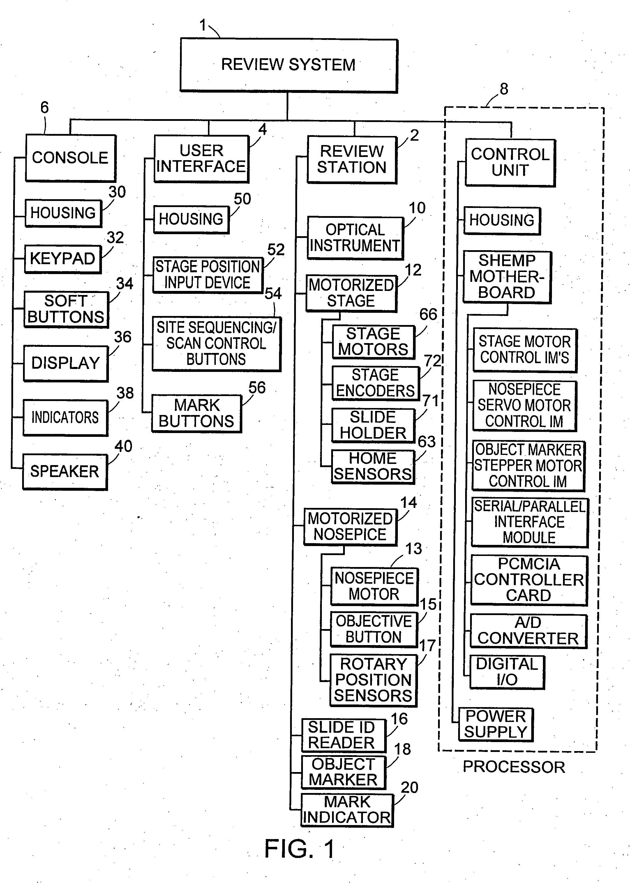
[0083] The review system (“RS”) defines apparatus used by a cytotechnologist or cytopathologist (collectively “user”) to view a slide having a cytological specimen disposed thereon. The review can be through either a customized optical instrument or a traditional microscope interface that utilizes automatic slide movement. The automatic movement presents fields of interest identified by an imaging system. Additionally, the review system provides a method for automated marking of objects for later review. The marking may be electrical, physical, or both.

[0084] Generally, when a user places a specimen on the RS for review, they are presented a plurality of fields of interest (“FOIs”) tha...


PUM


Abstract

The present invention relates to the analysis of specimens. Specifically, the invention relates to methods and apparatus for reviewing specimen slides, including apparatus for holding the slides. The invention also relates to an automatic focusing method for an imaging system and methods for accommodating vibration in the imaging system. In particular, the methods and apparatus may be applied to the automated analysis of cytological specimen slides.

Description

CROSS-REFERENCE TO RELATED APPLICATIONS [0001] This application is a continuation of co-pending U.S. application Ser. No. 10 / 008,379, filed on Nov. 5, 2001, which claims the benefit of provisional U.S. patent application Ser. No. 60 / 245,971, filed Nov. 3, 2000, and is a continuation-in-part of U.S. patent application Ser. No. 09 / 430,198, filed Oct. 29, 1999, and U.S. patent application Ser. No. 09 / 430,116, filed Oct. 29, 1999, the disclosures of which are hereby incorporated herein by reference in their entirety.TECHNICAL FIELD [0002] The present invention relates to systems and methods for the analysis of specimens. Specifically, the invention relates to a review system for reviewing specimens, methods of focusing the specimens in an imaging system, and apparatus for holding the specimen. BACKGROUND INFORMATION [0003] Cytology is the branch of biology dealing with the study of the formation, structure, and function of cells. As applied in a laboratory setting, cytologists, cytotech...

Claims


Application Information

Patent Timeline
IPC IPC(8): G02B21/34G01N1/30G01N15/10G01N15/14G01N21/31G02B21/00G02B21/32G06T7/00
CPCG01N1/30G01N15/1012G01N15/1463G01N15/1468G01N15/147G01N15/1475G01N21/3151G01N2015/1006G01N2015/1472G01N2015/1488G02B21/0016G02B21/32G02B21/34G06K9/00134G06T7/0012G06T7/0042G06T2207/30024G06T7/73G06V20/693G01N15/1433
Inventor ZAHNISER, DAVIDGEISELMAN, THEODORE S.OSTGAARD, ROYGREENE, HOWARD L.ZAMBANINI, JOSEPH E.JURATOVAC, JOSEPH A.ZELINSKI, MATTHEW S.DANHOF, SCOTT N.HASSENPFLUG, ERICHAUBERT, THOMAS D.CHINNOCK, RANDAL
Owner CYTYC CORP
Why Eureka
Try Eureka