
Systems and methods for providing continuous containment of delayed coker unit operations

a technology of delayed coker and containment method, which is applied in the direction of coke oven details, coke oven doors/closures, discharging devices, etc., can solve the problems of substantial operating delay, procedures required to minimize the potentially harmful effects, and create potential hazards for personnel, so as to simplify the decoking process

Active Publication Date: 2006-04-13
DELTAVALVE
View PDF37 Cites 16 Cited by
  • Summary
  • Abstract
  • Description
  • Claims
  • Application Information

AI Technical Summary

Benefits of technology

[0026] An advantage of the present invention is its ability to provide a simple, yet effective de-heading system comprising a de-header valve having a movable valve closure that oscillates or moves back and forth about the means for supporting the valve closure to de-head a coke drum and simplify the decoking process. Another advantage of the present invention is the ability to de-head the coke drum without having to physically remove the head or flange unit, and to do so at a remote location with little or no manual requirements. Other advantages will be apparent to one skilled in the art.
[0027] In a preferred embodiment, the means for supporting the valve closure comprises a seat support system. The seat support system may comprise any arrangement or configuration of seats, depending upon the type of valve, the needs of the system, system specifications, or any other contributing factors. In one exemplary configuration, the seat support system comprises an upper and lower seat existing on either side of the valve closure, wherein the upper seat and lower seat may be independent from one another. Still further, the upper and lower seat may be comprised of either a static or dynamic nature, such that one may be static and the other dynamic, both dynamic, or both static.
[0028] In another exemplary embodiment, the seat support system comprises a single seat situated or disposed between the main body of the de-header valve and the valve closure. In this configuration, the single seat applies a continuous force to the valve closure throughout its oscillation. The single seat may be a floating or dynamic seat, or it may be a static seat, again depending upon the type of valve, the needs of the system, system specifications, or any other contributing factors.
[0029] In several embodiments, the biasing necessary to maintain bug term sealing is provided by the gate itself. Several gates are biased against the seat to provide the same contact that would occur if the seat were biased toward the gate.
[0030] In a preferred embodiment, the seat support system advantageously provides a floating seat concept to the de-header valve using at least one dynamic, live loaded seat. This floating dynamic, live loaded seat is continuously loaded against the valve closure to create a biased relationship between the seat(s) and the valve closure. The floating seat concept is accomplished using one or a combination of biasing members, such as heavy coil springs arrayed at close centers around the perimeter of the seat ring; externally live loaded and sealed seat force applicators arrayed at quadrants around the floating seats; and / or a full perimeter flexible inconnel bellow seal spring placed between the floating seat and the seat retaining ring. One embodiment of the present invention utilizes a floating two piece gate to provide a floating seal with a static seat. The tow plates that form the gate are biased away from each other to seal against the seat. A floating or dynamic seat or gate provides many advantages, a primary one being that the seat support system and the valve closure are able to flex and distort in response to the rigorous and changing pressures and forces induced thereon during the coke manufacturing process and filling of the coke drum.
[0031] In another exemplary embodiment, means for supporting the valve closure comprises the main body itself. In this embodiment, no seats are required as various structural modifications can be made to the main body to support the valve closure. However, it is contemplated that a seat may be used to support the valve closure on one side and the main body on the other.

Problems solved by technology

Shot coke may also be loosely packed inside the drum and may “cave in” in an avalanche-like fashion and spilling onto the switch deck area below the coke drum causing substantial operating delay and creating potential hazards to personnel.
Procedures required to minimize the potentially harmful effects of a cave-in usually take a substantial amount of time and are not always completely effective.
If the drum contains shot coke further avalanches my occur.
This process may not be completely satisfactory in that there is exposure to an avalanche of shot coke when raising the chute and the chute may be overwhelmed or may not function in the event of a cave in.
Any of these steps can be hazardous to workers, but by far the most dangerous steps are in the transition from the coking phase to the decoking phase.
Workers are most frequently harmed while performing the following steps: (1) manually unlocking, disconnecting and separating the coke drum from the inlet pipe; (2) manually unlocking the drum-bottom closure from the coke drum; or (3) manually disengaging the drum-bottom closure from the coke drum.
Further workers are often harmed when pressurized gasses are released from the top of the deheading unit.
Coke is supposed to support itself in the coke drum when an opening is created at the drum-bottom; however, this cannot be assured.
The flow of loose coke and quench water or other materials from other types of vessels can be very hazardous for workers performing functions during the opening of the vessels.
This hazard exists until a secure passageway is present between the opening of the vessel and where the material is ultimately destined.
An even more hazardous environment is a coker design to produce “shot coke” where the coke will not support itself in the coke drum.
For all the above reasons, decoking a coke drum has been a relatively cautious and slow process especially when shot coke is produced and may expose workmen to a disagreeable and potentially dangerous environment.

Method used


Image

  • Systems and methods for providing continuous containment of delayed coker unit operations
  • Systems and methods for providing continuous containment of delayed coker unit operations
  • Systems and methods for providing continuous containment of delayed coker unit operations

Examples


Embodiment Construction

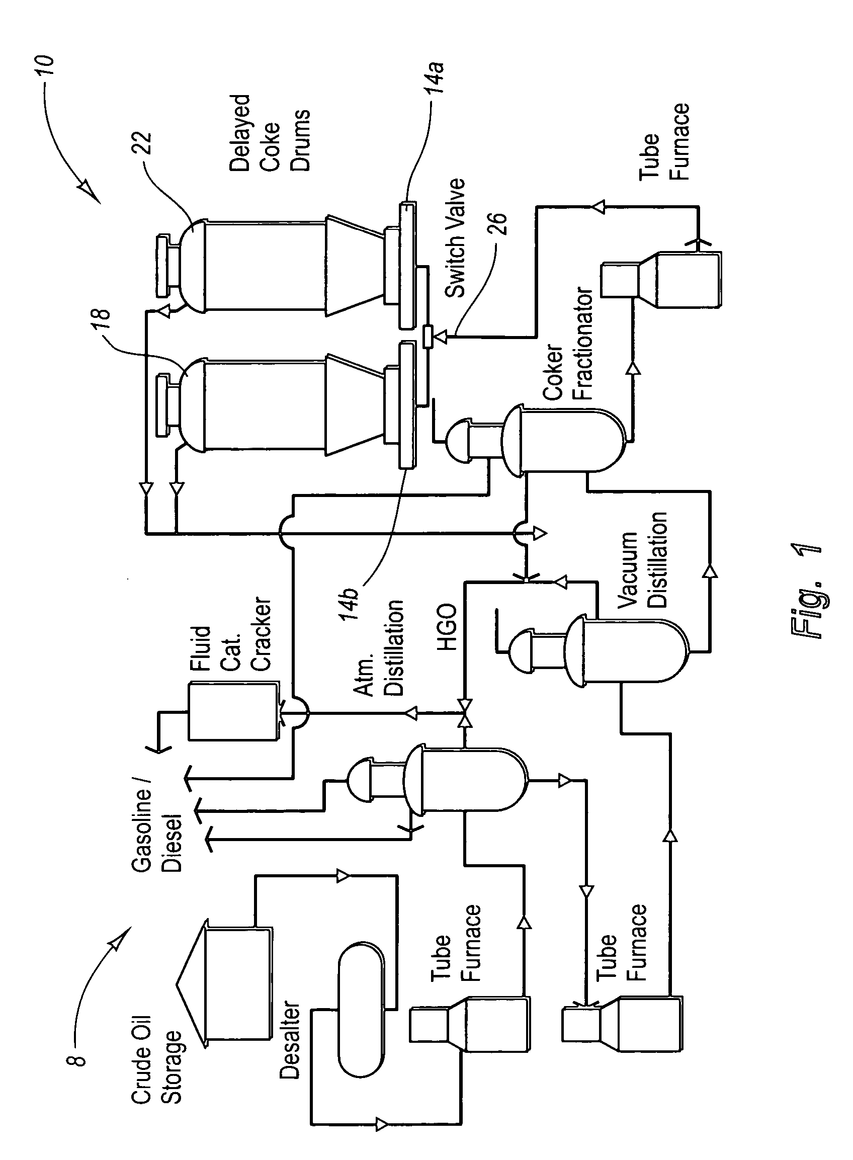
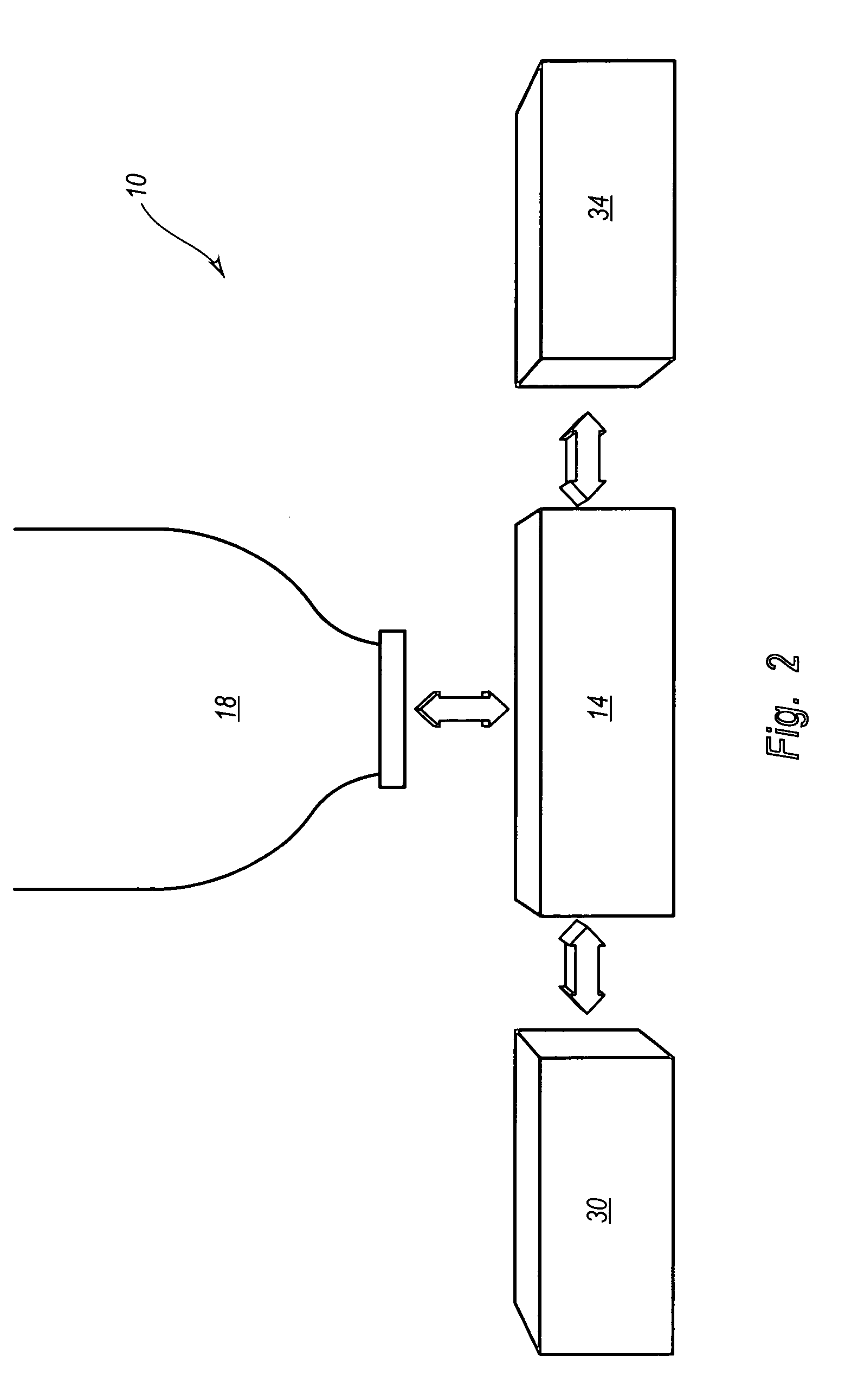
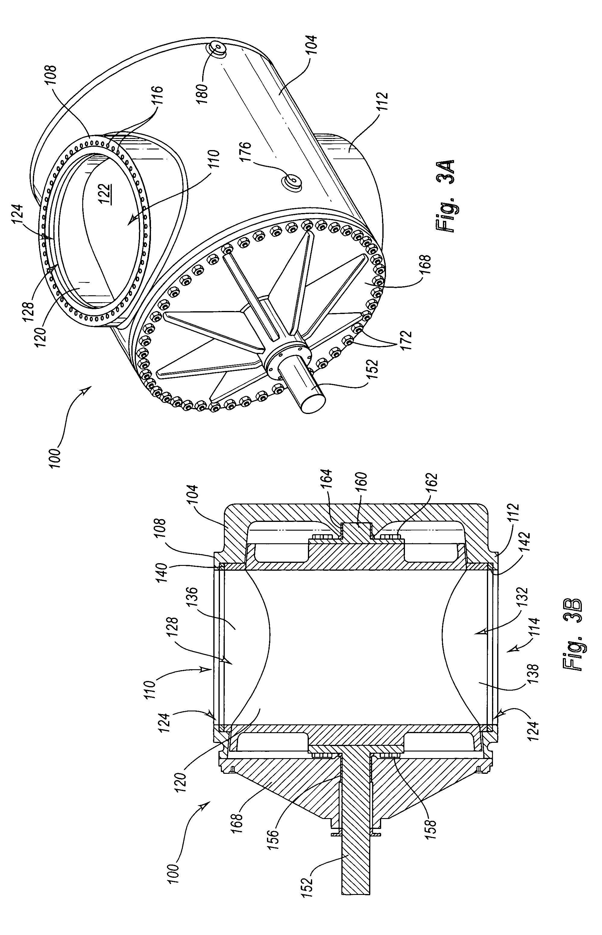
[0113] It will be readily understood that the components of the present invention, as generally described and illustrated in the figures herein, could be arranged and designed in a wide variety of different configurations. Thus, the following more detailed description of the embodiments of the system, device, and method of the present invention, as represented in FIGS. 1 through 45, is not intended to limit the scope of the invention, as claimed, but is merely representative of the presently preferred embodiments of the invention.

[0114] The presently preferred embodiments of the invention will be best understood by reference to the drawings wherein like parts are designated by like numerals throughout. Although reference to the drawings and a corresponding discussion follow below, the following more detailed description is divided into sections. The first section pertains to and sets forth a general discussion of the delayed coking process, including the process and effects of de-h...


PUM


Abstract

The present invention relates to a safety system during the entire delayed coker operation. The present invention preferably comprises a coke drum; a first coke drum de-header system coupled to the bottom of the coke drum; a second coke drum de-header system coupled to the top of the coke drum; a containment system coupled to the second coke drum de-header system; and a remote switching system. Hence, the present invention provides system for cutting coke within a coke drum with increased safety, efficiency and convenience.

Description

RELATED APPLICATIONS [0001] This application claims priority to U.S. Provisional Patent Application Ser. No. 60 / 607,373, filed Sep. 3, 2004, entitled, “Systems and Methods for Providing Continuous Containment of Drill Stem During Decoking;” and to and to U.S. patent application Ser. No. 10 / 997,234, filed Nov. 24, 2004, entitled, “Systems and Methods for Remotely Determining and Changing Cutting Modes During Decoking,” which claims priority to U.S. Provisional Patent Application Ser. No. 60 / 564,449 filed Apr. 22, 2004; and to U.S. patent application Ser. No. 10 / 997,834, filed Nov. 24, 2004, entitled “Valve System and Method for Unheading a Coke Drum,” which claims priority to U.S. patent application Ser. No. 10 / 731,874, filed Dec. 9, 2003, entitled, “Valve System and Method for Unheading Coke Drum,” and to U.S. patent application Ser. No. 10 / 096,301, filed Mar. 11, 2002, entitled, “Coke Drum Bottom De-Heading System,” now issued as U.S. Pat. No. 6,660,131; and to U.S. patent applicat...

Claims


Application Information

Patent Timeline
IPC IPC(8): C10B1/00C10B25/00C10B29/00
CPCC10B25/10C10B33/006C10B33/12
Inventor LAH, RUBEN F.
Owner DELTAVALVE
Learn More