Steam generator

a generator and steam technology, applied in the field of steam generators, can solve the problems of reducing the efficiency of the heating surface involved, reducing the steam generation, and unsatisfactory efficiency losses, and achieve the effects of stable and reliable throughflow of steam-generating pipes, low friction pressure loss, and low startup cos

Inactive Publication Date: 2006-04-13
SIEMENS AG
View PDF6 Cites 17 Cited by
  • Summary
  • Abstract
  • Description
  • Claims
  • Application Information

AI Technical Summary

Benefits of technology

[0008] An object of the invention is thus to specify a steam generator of the type stated above which is particularly cheap to build and which also exhibits an especially high mechanical stability at different thermal loading.

Problems solved by technology

Especially with steam generation pipes connected on the output side to a common collector, a different heating of individual steam generation pipes can result in a merging of steam flows with sharply differing steam parameters and thereby to undesired losses of efficiency, especially to a comparatively reduced effectiveness of the heating surface involved and thereby to reduced steam generation.
A different heating of adjacent steam-generating pipes can also, especially in the inlet area of collectors, lead to damage to the steam-generating pipes or to the collector.
The use of a horizontal design of throughflow steam generator, which is desirable per se, as a waste heat steam generator for a gas turbine, can thus present significant problems as regards a sufficiently stabilized flow feed.
However the known steam generator is comparatively expensive to construct, especially as regards the water and / or heat-side distribution of the flow medium.

Method used


Image

  • Steam generator
  • Steam generator

Examples


Embodiment Construction

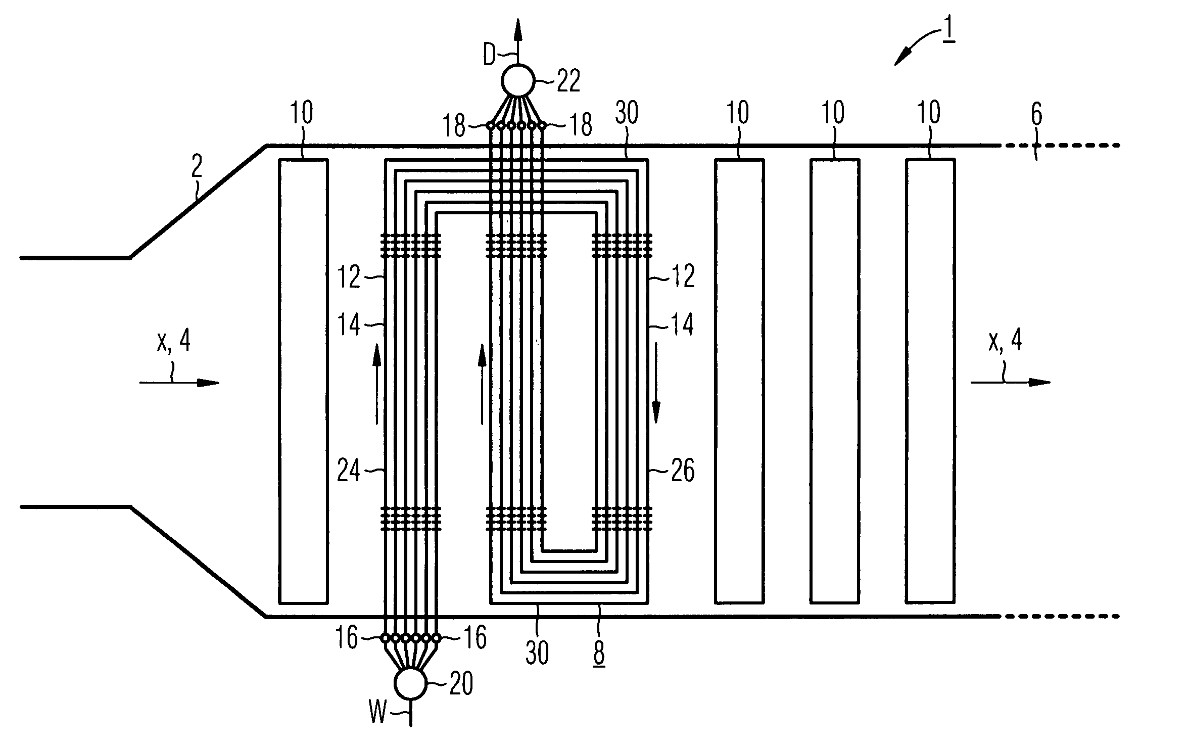
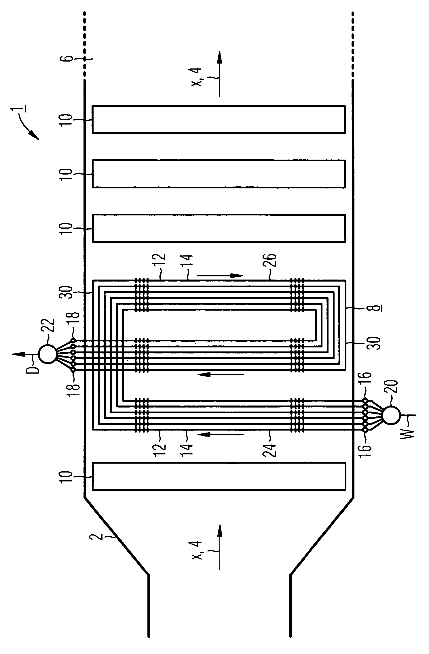
[0026] The steam generator 1 in accordance with the Figure is connected downstream as a type of waste heat stem generator from a gas turbine not shown in any greater detail. The steam generator 1 features a surrounding wall 2 which forms a heating gas duct 6 through which flow is possible in an almost horizontal heating gas direction x, indicated by the arrows 4 for the exhaust gas from the gas turbine. In the heating gas duct 6 are a number of heating surfaces each arranged in accordance with the throughflow principle, also designated as the continuous evaporation heating surface 8, which are provided for the evaporation of the flow medium. Only one continuous evaporating heating surface 8 is shown in the exemplary embodiment in accordance with the Figure, but a larger number of continuous evaporating heating surfaces can be provided.

[0027] The evaporation system formed from the continuous evaporating heating surface 8 can have a flow medium W applied to it which evaporates on a s...


PUM


Abstract

A stream generator wherein a continuous evaporating heating surface is disposed in a heating gas duct through which a heating gas flows in an approximately horizontal manner. The continuous evaporating heating surface comprises a plurality of steam-generating pipes which are connected in a parallel manner enabling flowthrough of a flow medium, and is configured in such a manner that a steam-generating pipe which is heated more than another stream-generating pipe of the same continuous evaporating heating surface has a higher throughput of a flow medium compared to the other steam-generating pipe. An object is to produce a particularly low-cost steam generator exhibiting particularly high mechanical stability with different thermal loads. The steam-generating pipe respectively comprises a riser pipe piece which can be cross-flown in an upward direction and which is arranged in an approximately vertical manner in relation to the flow medium; a down pipe piece which can be cross-flown in a downward direction downstream from said flow medium side and another riser pipe piece which can be cross-flown in an upward direction by a flow medium and which is arranged in an approximately vertical manner downstream from the latter flow medium side. Preferably, the other riser pipe piece of the respective steam-generating pipe is arranged in the heating gas duct, when seen in the direction of the heating gas, between the riser pipe piece associated therewith and the down pipe piece associated therewith.

Description

CROSS REFERENCE TO RELATED APPLICATIONS [0001] This application is the US National Stage of International Application No. PCT / EP2003 / 013879, filed Dec. 8, 2003 and claims the benefit thereof. The International Application claims the benefits of European application No. 03002243.8 EP filed Jan. 31, 2003, all of the applications are incorporated by reference herein in their entirety. FIELD OF INVENTION [0002] The invention relates to a steam generator wherein a continuous evaporating heating surface is disposed in a heating gas duct through which gas flows in an approximately horizontal manner, said continuous evaporating heating surface comprising a plurality of steam-generating pipes which are connected in a parallel manner, enabling flowthrough of the flow medium and is configured in such a manner that a steam generating pipe which is heated more than another steam generating pipe of the same continuous evaporating heating surface has a higher throughput of the flow medium compared...

Claims


Application Information

Patent Timeline
IPC IPC(8): F22D7/00F22B1/18
CPCF22B1/1815F22B1/18
Inventor FRANKE, JOACHIMKRAL, RUDOLF
Owner SIEMENS AG
Why Eureka
Try Eureka