Ride control circuit for a work machine

a control circuit and work machine technology, applied in the direction of fluid couplings, couplings, mechanical equipment, etc., can solve the problems of increased operator fatigue, uncompromising ride, and shocks of the hydraulic boom holding the payload

Inactive Publication Date: 2006-04-13
CATERPILLAR INC
View PDF3 Cites 26 Cited by
  • Summary
  • Abstract
  • Description
  • Claims
  • Application Information

AI Technical Summary

Benefits of technology

[0008] According to the present disclosure, there is provided a hydraulic ride control circuit for a work machine having a loader arm, the circuit including a hydraulic ram having first and second chambers, the ram being adapted to raise and lower the loader arm. A first control valve is connected to the first and second chambers and adapted to feed pressurised fluid to one of the first and second chambers so as to selectively raise or lower the loader arm. A load hold valve is located between the first control valve and first chamber, the load hold valve having a hydraulic control surface and being movable between a first position in which fluid flow from the first chamber to the first control valve is prevented, and a second position in which fluid flow from the first chamber to the first control valve is permitted. A pressure-monitoring line connects the second chamber and the control surface of the load hol...

Problems solved by technology

When a work machine such as a telehandler is carrying a payload over rough terrain, the hydraulic boom holding the payload experiences shocks from movements of the payload.
This makes the machine more susceptible to pitch and bounce, resulting in an uncompromising ride and an increase in operator fatigue.
One dis...

Method used


Image

  • Ride control circuit for a work machine
  • Ride control circuit for a work machine
  • Ride control circuit for a work machine

Examples


first embodiment

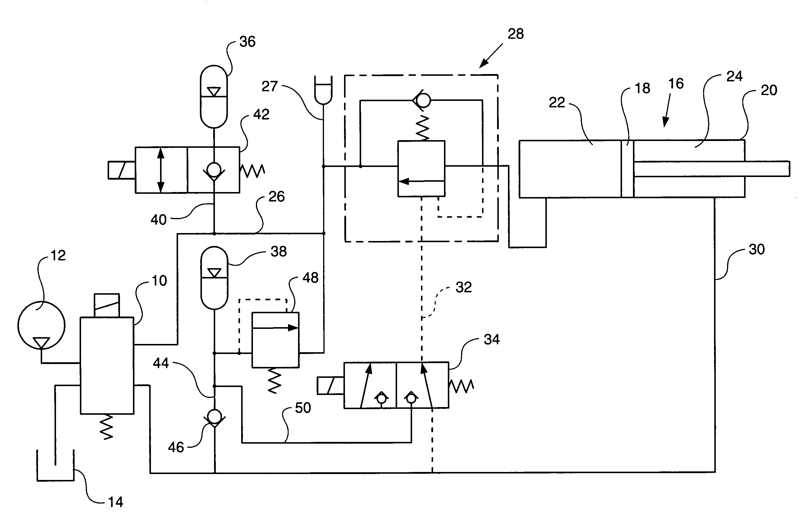
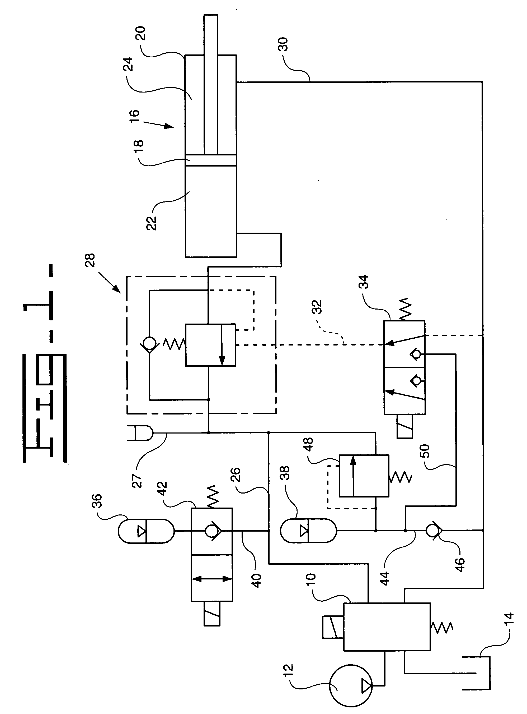
[0021] This first embodiment of the ride control circuit is able to provide the ride control function alongside the normal raising and lowering of the boom. If the boom is to be operated while the ride control function is engaged, a signal is sent to the second and third control valves 42, 34 and the valves 42, 34 are de-energized, closing off the pressure from the accumulators 36, 38. Once the boom operation is complete, a further signal re-energizes the valves 42, 34 and the ride control function is re-engaged.

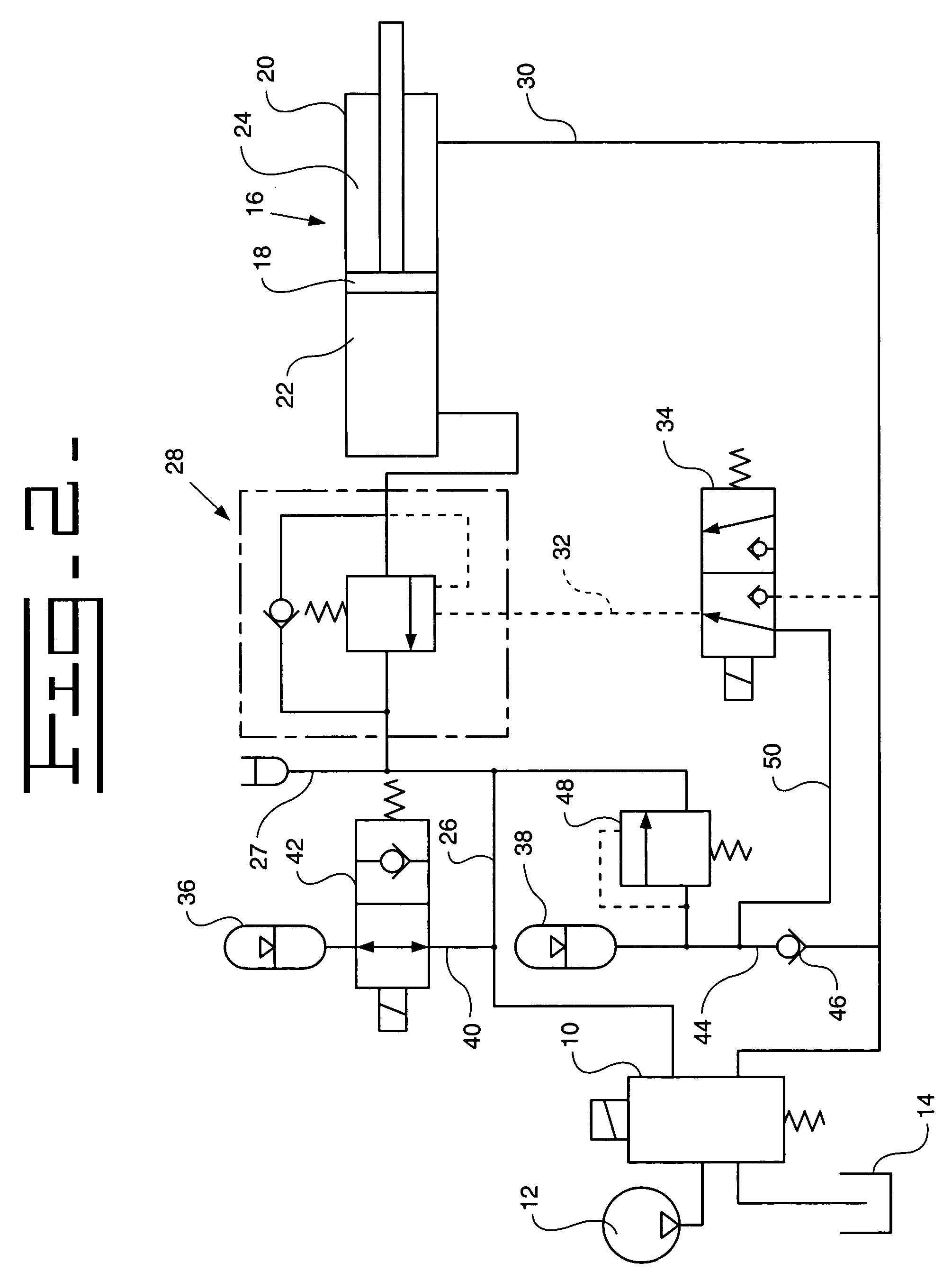
[0022]FIG. 3 illustrates a second embodiment of the ride control circuit. The second embodiment of the circuit shares the majority of its components with the first embodiment described above. Those shared components are designated by the same reference numbers as used to describe the first embodiment, and consequently will not be described further here. Where the second embodiment differs from the first embodiment is that the load hold valve 28′ of the second embodiment incl...

second embodiment

[0034] Although the second embodiment described in FIG. 3 uses a pressure-varying valve in order to vary the pressure on the control surface of the load hold valve, it should be understood that any suitable pressure-varying means could be used instead.

[0035] Furthermore, although in the embodiments described above, the ride control function is temporarily disengaged when a boom raise or lower is required, the circuit of the present disclosure is also capable of carrying out a boom raise or lower without the need to disengage the ride control disclosure.


PUM


Abstract

A hydraulic circuit for raising and lowering a load arm on a work machine is adapted to provide a ride control function which will cushion shocks through the load arm as the machine traverses rough terrain. The circuit includes a hydraulic ram that moves the load arm and a first hydraulic accumulator connected to a first chamber of a hydraulic ram. The accumulator provides a cushioning effect to the ram when the ride control function is engaged. The accumulator is located between a first control valve and a load hold valve of the circuit so that the load hold valve will hold the ram in position should there be any sudden pressure drop in or adjacent the accumulator. The accumulator can also be connected to a control surface of the load hold valve to simultaneously open the valve and cushion the ram. A second dedicated accumulator can also be introduced for this purpose if desired.

Description

TECHNICAL FIELD [0001] The present disclosure relates to the field of work machines. More specifically, the present disclosure relates to a ride control circuit for use in work machines that include a hydraulic boom arrangement, such as wheeled loaders and telehandlers. BACKGROUND [0002] When a work machine such as a telehandler is carrying a payload over rough terrain, the hydraulic boom holding the payload experiences shocks from movements of the payload. These shocks are usually transferred directly to the machine via the boom. This makes the machine more susceptible to pitch and bounce, resulting in an uncompromising ride and an increase in operator fatigue. Hydraulic ride control circuits, that is hydraulic circuits that improve the ride quality of a work machine, are known. Such circuits conventionally selectively connect a hydraulic accumulator with the hydraulic ram arrangement of the boom in order to cushion any shocks experienced by the boom and ram. In cushioning the shoc...

Claims


Application Information

Patent Timeline
IPC IPC(8): F16D31/02B66F9/22E02F9/22
CPCB66F9/22E02F9/2207B66F9/065E02F9/22
Inventor EVANS, TERENCE
Owner CATERPILLAR INC
Why Eureka
Try Eureka