
Amplifier and sub-woofer speaker system

Inactive Publication Date: 2006-04-06
BROAN NUTONE
View PDF15 Cites 25 Cited by
  • Summary
  • Abstract
  • Description
  • Claims
  • Application Information

AI Technical Summary

Benefits of technology

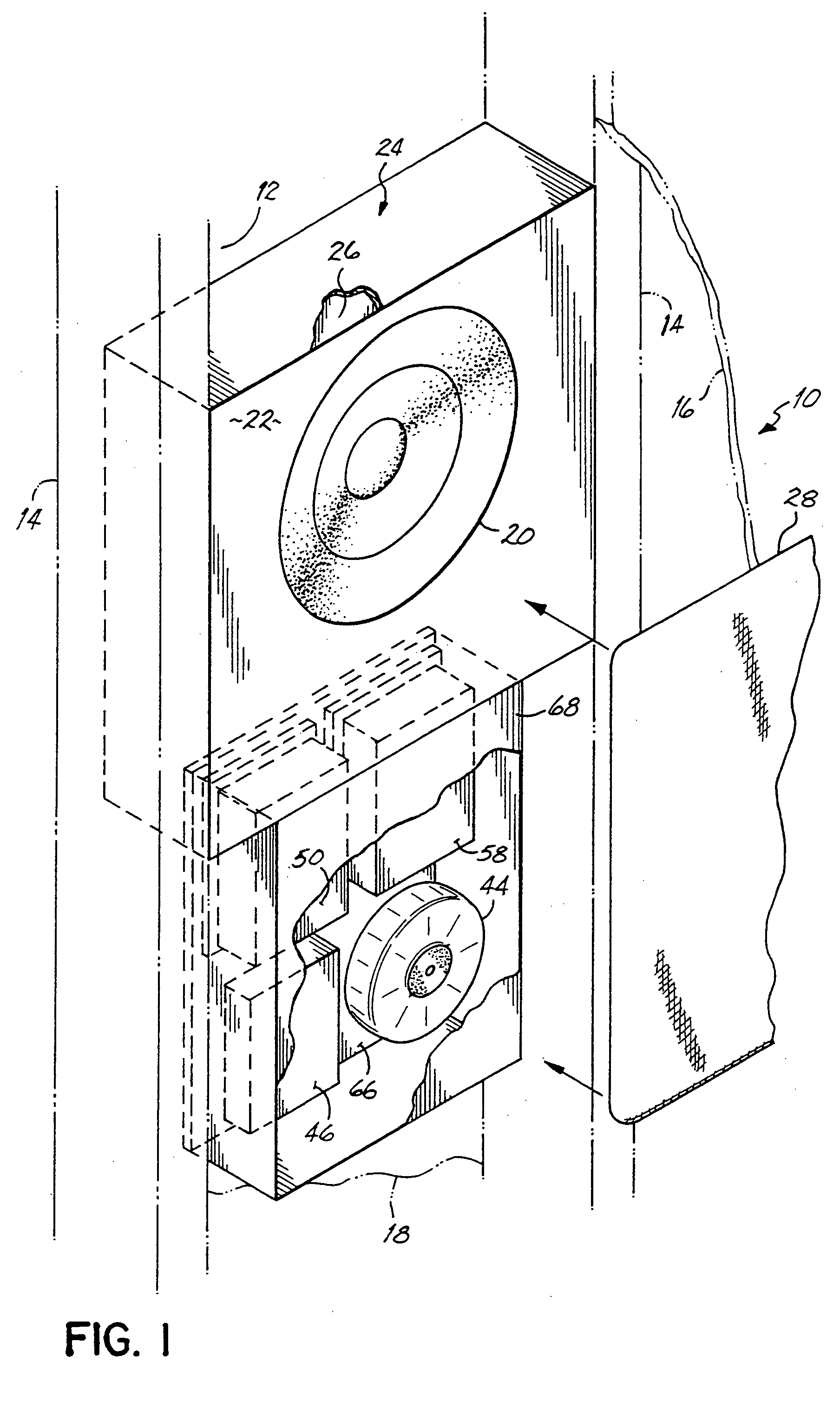
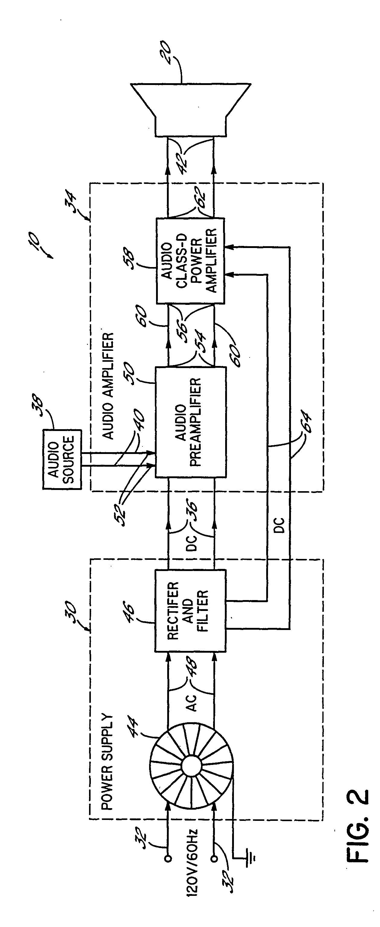
[0011] Some embodiments of the present invention provide a sub-woofer speaker system designed to be mounted in a closely confined space such as a house wall cavity, ceiling, floor or other enclosure. In some embodiments, the sub-woofer speaker system includes a power supply circuit, an audio amplifier circuit powered by the power supply circuit, and a subwoofer audio driver that is driven by the audio amplifier circuit. Low frequency audio signals are coupled from an audio source, such as a stereo amplifier or home entertainment system, to the audio amplifier circuit of the subwoofer speaker system. The audio signals are amplified by the audio amplifier and coupled to the subwoofer audio driver for reproduction of the low frequency audio information within a listening area. The subwoofer audio driver can have a diameter of about ten (10) inches to give an enhanced, realistic listening experience to the listener.
[0012] In some embodiments, the power supply circuit of the sub-woofer speaker system includes a toroidal power transformer coupled to a rectifier and filter circuit. The toroidal power transformer typically has a minimum efficiency of about 90%, and negligible leakage inductance and stray capacitance. Due to its relatively high efficiency, the toroidal power transformer is significantly smaller than conventional E-1 laminated transformers.
[0013] The audio amplifier circuit in some embodiments includes an audio preamplifier circuit having an audio input adapted to be coupled to the audio signal source and an audio output coupled to a class-D audio amplifier. The class-D audio amplifier typically has a minimum efficiency of about 90%. Due to its relatively high efficiency and minimal heat loss, the class-D power amplifier is significantly smaller and lighter than conventional class-AB audio amplifiers. Each of the audio preamplifier circuit and class-D audio amplifier circuit can be coupled to the rectifier and filter circuit for receiving DC power therefrom. In some embodiments, a sub-woofer audio driver is coupled to an audio output of the class-D amplifier and is operable to produce low frequency audio information in response to audio signals coupled to the preamplifier circuit from the audio source. The power supply circuit, the audio amplifier circuit, and the sub-woofer audio driver can have a low profile, such as a depth of less than about four (4) inches, so the sub-woofer speaker system can be readily mounted in a closely confined space such as a house wall cavity, floor, ceiling or other low profile enclosure.
[0014] It will be appreciated that a high-efficiency transformer (e.g., a minimum 90% efficiency toroidal power transformer with negligible leakage inductance and stray capacitance) can permit a smaller power transformer to be used in the sub-woofer speaker system of the present invention over the conventional E-1 laminated power transformers of the past. Moreover, it will also be appreciated that a high-efficiency amplifier (e.g., a 90% efficiency digital class-D audio amplifier with minimal heat loss) can permit a smaller and lighter audio amplifier to be used in the sub-woofer speaker system of the present invention over the conventional class-AB audio amplifiers of the past. The combination of a toroidal power transformer, class-D audio amplifier, and sub-woofer audio driver, each having a low profile of less than about four (4) inches, permits the sub-woofer speaker system of the present invention to be readily mounted in a closely confined space for reproducing low frequency audio information from an audio source.

Problems solved by technology

Sound systems, for the most part, were limited to a small speaker built into a television, and few people had television screens larger than 27 inches.
There was certainly no mistaking the typical TV room for a home theater—home theaters were expensive setups, often having actual film projectors and wide screens.
Conventional entertainment systems still often lack high quality sound typically found only in theaters, concert halls, and other venues.
Also, few options are available for placement of conventional entertainment system components, resulting in undesirable system and room arrangements, disorganized and / or unsightly entertainment systems, and other shortcomings.
In many cases, it is not possible to easily place many entertainment system components in a variety of locations.
For example, many sound systems have amplifiers that are intended to be stored in a cabinet or entertainment system rack, thereby limiting the locations for placement of such units.
As another example, subwoofer speakers are normally relatively large devices that do not fit well into many rooms.
However, these low frequencies cannot be reproduced by conventional smaller woofers so larger audio drivers or speakers cones having a diameter of ten (10) inches or more are typically used in sub-woofer speaker systems.
Accordingly, the ability to locate such a large device in desired locations in a room is often limited.
Powered sub-woofers typically find use in applications where a local amplifier of a stereo or home entertainment system is limited in its output power and cannot drive the sub-woofer to its full efficiency.
Therefore, passive sub-woofers are generally not able to produce the same sound level as powered sub-woofers due to the limited output power of most conventional stereo amplifiers.
However, class-AB audio amplifiers generally have a relatively low efficiency so a significant amount of input power to the amplifier is wasted as heat.
Massive aluminum heat sinks are therefore used to keep the class-AB audio amplifier cool, which leads to increased size, weight, and cost of such amplifiers.
However, E-1 laminated transformers tend to be relatively large due to their relative inefficiency and therefore preclude the use of conventionally powered sub-woofer speaker systems in closely confined spaces such as a house wall cavity.

Method used


Image

  • Amplifier and sub-woofer speaker system
  • Amplifier and sub-woofer speaker system
  • Amplifier and sub-woofer speaker system

Examples


Embodiment Construction

[0036] Before embodiments of the invention are explained in detail, it is to be understood that the invention is not limited in its application to the details of the examples set forth in the following description or illustrated in the drawings. The invention is capable of other embodiments and of being practiced or carried out in a variety of applications and in various ways. Also, it is to be understood that the phraseology and terminology used herein is for the purpose of description and should not be regarded as limiting. The use of “including,”“comprising,” or “having” and variations thereof herein is meant to encompass the items listed thereafter and equivalents thereof as well as additional items. The terms “mounted,”“connected,” and “coupled” are used broadly and encompass both direct and indirect mounting, connecting, and coupling. Further, “connected” and “coupled” are not restricted to physical or mechanical connections or couplings.

[0037] With reference to FIGS. 1 and 5...


PUM


Abstract

Some embodiments of the present invention employ a subwoofer speaker adapted to be recessed within a wall or other building structure. In another aspect of the present invention, an amplifier is adapted to be recessed within a wall or other building structure, and can be employed with the recessed subwoofer or with another component of an entertainment system. In some embodiments, the subwoofer speaker is mounted in a wall cavity and supported therein with brackets. If desired, the amplifier can be supported by a frame within a wall cavity.

Description

[0001] This application is a continuation-in-part of U.S. patent application Ser. No. 09 / 466,487 filed on Dec. 17, 1999.BACKGROUND OF THE INVENTION [0002] Twenty five years ago, only a small percentage of households had cable television, and VCRs were a new luxury item. Sound systems, for the most part, were limited to a small speaker built into a television, and few people had television screens larger than 27 inches. There was certainly no mistaking the typical TV room for a home theater—home theaters were expensive setups, often having actual film projectors and wide screens. [0003] Over the years, the world of home entertainment has changed radically. Currently, many U.S. households have at least 50 television channels, a large color television, and a VCR and / or a DVD player. More and more households are adding additional advanced components to their entertainment setup to create home theater systems. Spurred by new technology triggering new product development, the world of hom...

Claims


Application Information

Patent Timeline
IPC IPC(8): H04R1/02H04R3/00
CPCH04R1/025H04R3/00H04R2201/021
Inventor VISHWAMITRA, TEJASWI
Owner BROAN NUTONE
Learn More