Primary sided-arrangement of primary winding structures, a method of manufacturing the primary-sided arrangement, a system for inductive power transfer and a method for inductively supplying power to a vehicle

a primary winding structure and primary sided arrangement technology, applied in the direction of charging stations, cores/yokes, transportation and packaging, etc., to achieve the effect of reducing the reactive power, increasing the inductive power transfer performance, and reducing the amount of conduction loss within these sections of the primary side winding structur

Active Publication Date: 2019-12-17
IPT GRP BV
View PDF18 Cites 0 Cited by
  • Summary
  • Abstract
  • Description
  • Claims
  • Application Information

AI Technical Summary

Benefits of technology

[0029]The proposed primary-sided arrangement advantageously allows to improve the efficiency of inductive power transfer if a secondary winding structure can be arranged with different positions and / or orientations relative to the primary winding structure. In particular, the minimum efficiency for a selected set of different positions and / or orientations can be maximized by adapting the pitches and / or the length of subwinding structures.
[0145]Controlling two of the three operating currents such that their respective current curves are equal can e.g. increase the current within a phase line providing a fully covered section of primary winding structure, wherein currents in a phase line providing a partially-exposed section of the primary winding structure will be reduced. By reducing the current in the phase lines providing partially-exposed sections of the primary side winding structure, the amount of conduction loss within these sections of the primary side winding structure will reduce advantageously. By a higher current in the phase line providing the fully-covered primary side windings, the range of acceptable misalignments will be advantageously expanded.

Problems solved by technology

There is the technical problem of providing a primary-sided arrangement of primary winding structures of a system for inductive power transfer, a system for inductive power transfer and a method of inductively transferring power to a vehicle, wherein the efficiency of the power transfer is maximized for varying relative positions and / or orientations between the primary winding structure and the secondary winding structure.

Method used


Image

  • Primary sided-arrangement of primary winding structures, a method of manufacturing the primary-sided arrangement, a system for inductive power transfer and a method for inductively supplying power to a vehicle
  • Primary sided-arrangement of primary winding structures, a method of manufacturing the primary-sided arrangement, a system for inductive power transfer and a method for inductively supplying power to a vehicle
  • Primary sided-arrangement of primary winding structures, a method of manufacturing the primary-sided arrangement, a system for inductive power transfer and a method for inductively supplying power to a vehicle

Examples


Embodiment Construction

[0180]In the following, the same numerals denote elements with the same or similar technical features.

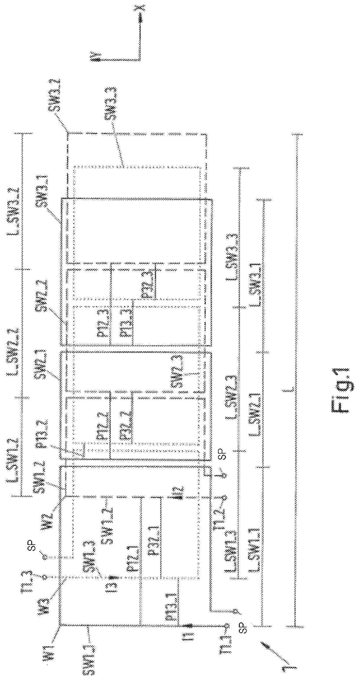
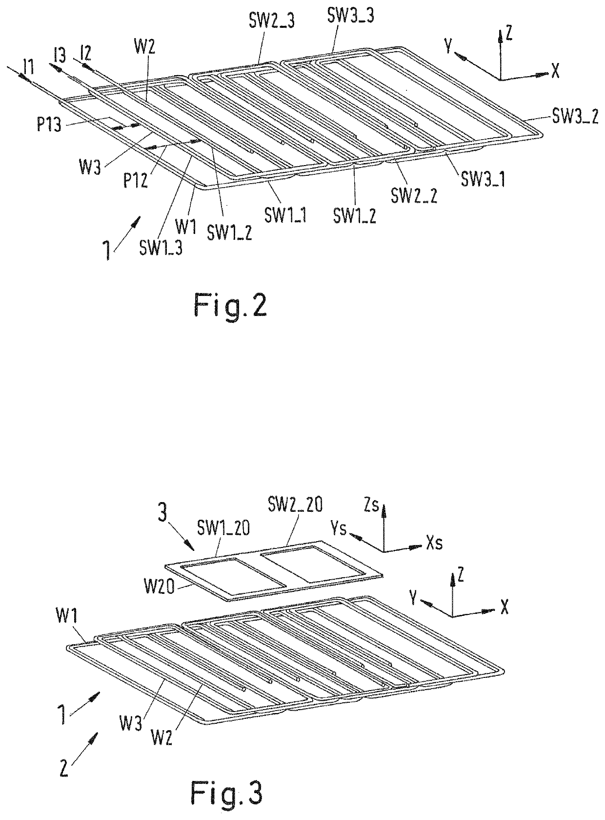
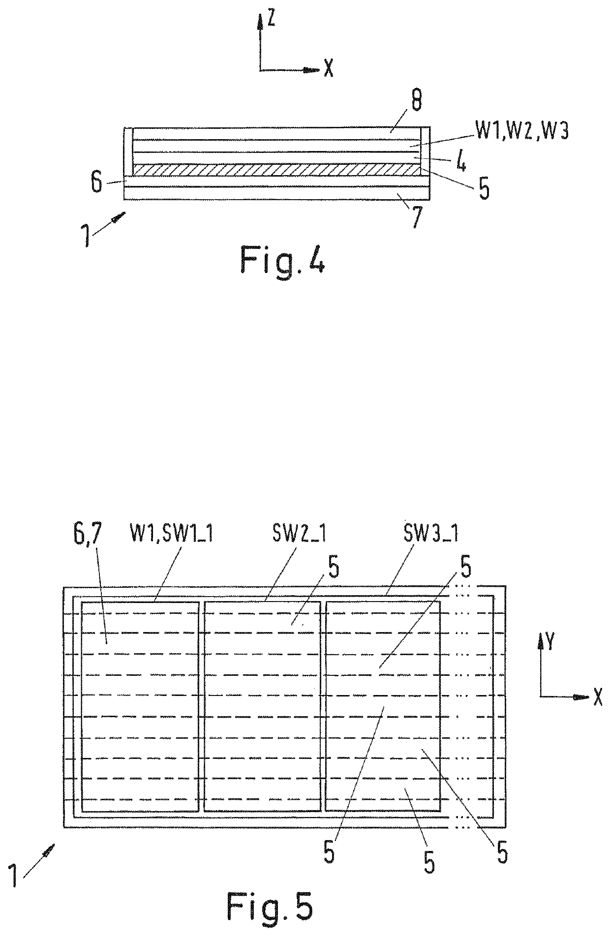
[0181]FIG. 1 shows a schematic top view on a primary-sided arrangement 1 of primary winding structures W1, W2, W3 of a system 2 for inductive power transfer (see FIG. 4). The primary-sided arrangement 1 comprises a first winding structure W1 with three subwinding structure SW1_1, SW2_1, SW3_1. Further, the primary-sided arrangement 1 comprises a second winding structure W2 and a third winding structure W3 which also have three subwinding structures SW1_2, SW2_2, SW3_2, SW1_3, SW2_3, SW3_3, respectively. These winding structures W1, W2, W3 provide each a phase line of a three phase topology. In the example shown in FIG. 1, the subwindings SW1_1, . . . , SW3_3 have the shape of a rectangular loop.

[0182]Further shown is a primary-sided coordinate system with a primary-sided longitudinal axis x and a primary-sided lateral axis y. Directions of these axes x, y are indicated by arrows. Th...


PUM

PropertyMeasurementUnit
phase angleaaaaaaaaaa
distanceaaaaaaaaaa

Abstract

The invention relates to a primary-sided arrangement (1) of primary winding structures (W1, W2, W3) of a system for inductive power transfer, wherein the primary-sided arrangement (1) comprises at least three phase lines and at least one winding structure (W1, W2, W3) per phase line, wherein each winding structure (W1, W2, W3) comprises at least one subwinding structure (SW1_1, . . . , SW3_3), wherein the winding structures (W1, W2, W3) extend along a longitudinal axis (x) of the primary-sided arrangement (1), wherein a pitch (P12_1, . . . , P32_3) between corresponding subwinding structures (SW1_1, . . . , SW3_3) of the winding structures (W1, W2, W3) varies along the longitudinal axis (x) and / or a length (L_SW1_1, . . . , LSW1_3) of the subwinding structures (SW1_1, . . . , SW3_3) of the winding structures (W1, W2, W3) varies along the longitudinal axis (x). The invention further relates to a system for inductive power transfer, to a method of manufacturing a primary-sided arrangement (1) and to a method for inductively supplying power to a vehicle.

Description

CROSS-REFERENCE TO RELATED APPLICATIONS[0001]This application is the United States national phase of International Application No. PCT / EP2016 / 064557 filed Jun. 23, 2016, and claims priority to United Kingdom Patent Application Nos. 1511259.2, 1512275.7, and 1607032.8, filed Jun. 26, 2015, Jul. 14, 2015, and Apr. 22, 2016, respectively, the disclosures of which are hereby incorporated in their entirety by reference.BACKGROUND OF THE INVENTIONField of the Invention[0002]The invention relates to a primary-sided arrangement of primary winding structures of a system for inductive power transfer. Further, the invention relates to a method of manufacturing such a system. Further, the invention relates to such a system for inductive power transfer and a method for inductively transferring power to a vehicle.Description of Related Art[0003]Electric vehicles, in particular a track-bound vehicle, and / or a road automobile, can be operated by electric energy which is transferred by means of an i...

Claims


Application Information

Patent Timeline
Patent Type & Authority Patents(United States)
IPC IPC(8): B60L53/12H01F38/14B60L53/30H01F3/10H01F27/28H02J50/10H01F41/04
CPCB60L53/30H01F27/28H01F38/14B60L53/12H01F3/10H02J50/10Y02T10/7005Y02T90/12Y02T10/7088Y02T90/122H01F41/04Y02T90/14B60L53/305B60L53/126Y02T10/7072Y02T90/16Y02T10/70B60Y2200/91
Inventor WIRTH, CHRISTIANCZAINSKI, ROBERTLINDT, RUDOLF
Owner IPT GRP BV
Why Eureka
Try Eureka