
Safety device for garage door

Inactive Publication Date: 2006-04-06
EQUUS
View PDF2 Cites 12 Cited by
  • Summary
  • Abstract
  • Description
  • Claims
  • Application Information

AI Technical Summary

Benefits of technology

[0010] The present invention is to provide a garage door safety device that can significantly and extensively increase the safety of a garage door.
[0012] The light transmitter emits light beam to be reflected in a number of times by the light guiding mirrors and to be received by the receiver so that a light traveling path constructs an extensive sensing network to make the control mechanism capable of responding immediately when the garage door is closing and subject to blockage to stop closing action and return to open state. Therefore, the safety is improved when people, cars or objects are moving in and out of a garage.

Problems solved by technology

This can end up with an accident.
It cannot assure the safety of a garage door completely.
It also lacks flexibility and applicability.
Secondly, if the transmitter and the receiver adopt cable devices, the sensing devices connect to the door control mechanism through electrical wires.
This causes inconvenience for installation.
Besides, the wire is easy to get damaged and needs difficult maintenance.
This adds extra difficulty to safety control.
On the other hand, the layout and exposure of the wire affects the aesthetics of garage interior.
Overly arranged wiring further creates a disorganized feeling.
Furthermore, if the transmitter and the receiver adopt wireless devices (battery inside), battery replacement is needed when the power is out, otherwise the sensing device will not work and bring about safety concerns for people, cars and objects.
This structure applied to the garage door safety device will make cost too high.
In addition, lots of wires are needed, which will cause messy arrangement and difficult maintenance of those wires.

Method used


Image

  • Safety device for garage door
  • Safety device for garage door
  • Safety device for garage door

Examples


Embodiment Construction

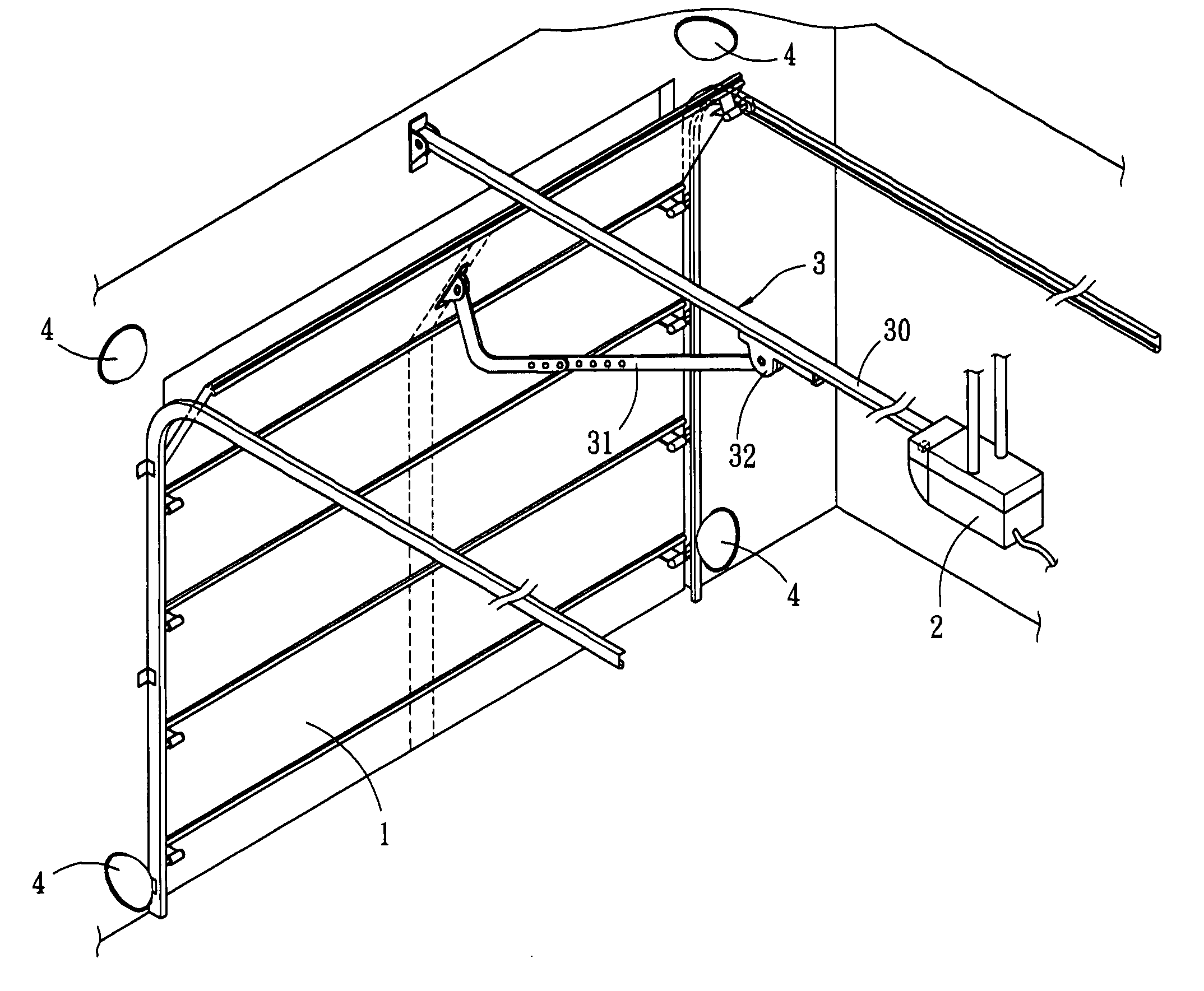
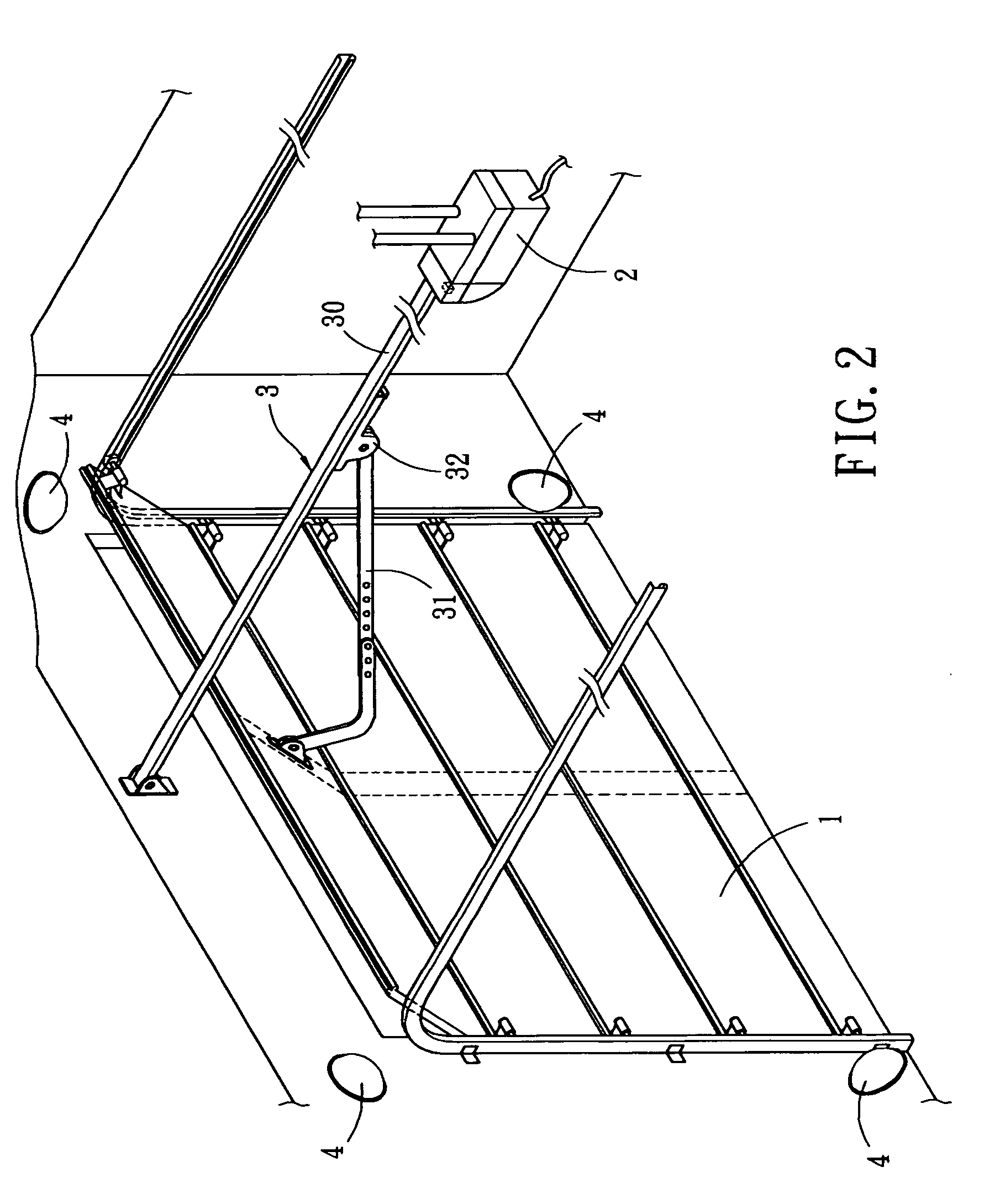
[0017] Please refer to FIG. 2, a safety device for garage door of the present invention includes a garage door 1, a control mechanism 2, a movement mechanism 3 and a plurality of light guiding mirrors 4.

[0018] The garage door 1 includes a plurality of plates connected together. A plurality of rollers are mounted on two sides of the garage door 1. Two L-shaped track is installed beside each side of the garage door 1 so that the rollers can move along the tracks to have the garage door 1 open or close.

[0019] The control mechanism 2 for controlling the garage door 1 is fixed on the garage ceiling near the rear ends of the tracks. The control mechanism 2 includes a motor and a driving device connected to the motor. A light transmitter 20 and a light receiver 21 are installed inside the control mechanism 2.

[0020] The light guiding mirror 4 is disposed on a location adjacent to each of four corners of the garage door 1. Preferably, the light guiding mirror 4 is a paraboloidal mirror.

[...


PUM


Abstract

A safety device of a garage door includes a light guiding mirror disposed on a location adjacent to each of four corners of the garage door. A transmitter and a receiver are installed in a garage door control mechanism. Through the surrounding light guiding mirrors, the light emitted from the transmitter is reflected in a number of times by the light guiding mirrors and to be received by the receiver so that a light traveling path constructs an extensive sensing network to make the control mechanism capable of responding immediately when the garage door is closing and subject to blockage to stop closing action and return to open state. Therefore, the safety is improved when people, cars or objects are moving in and out of a garage.

Description

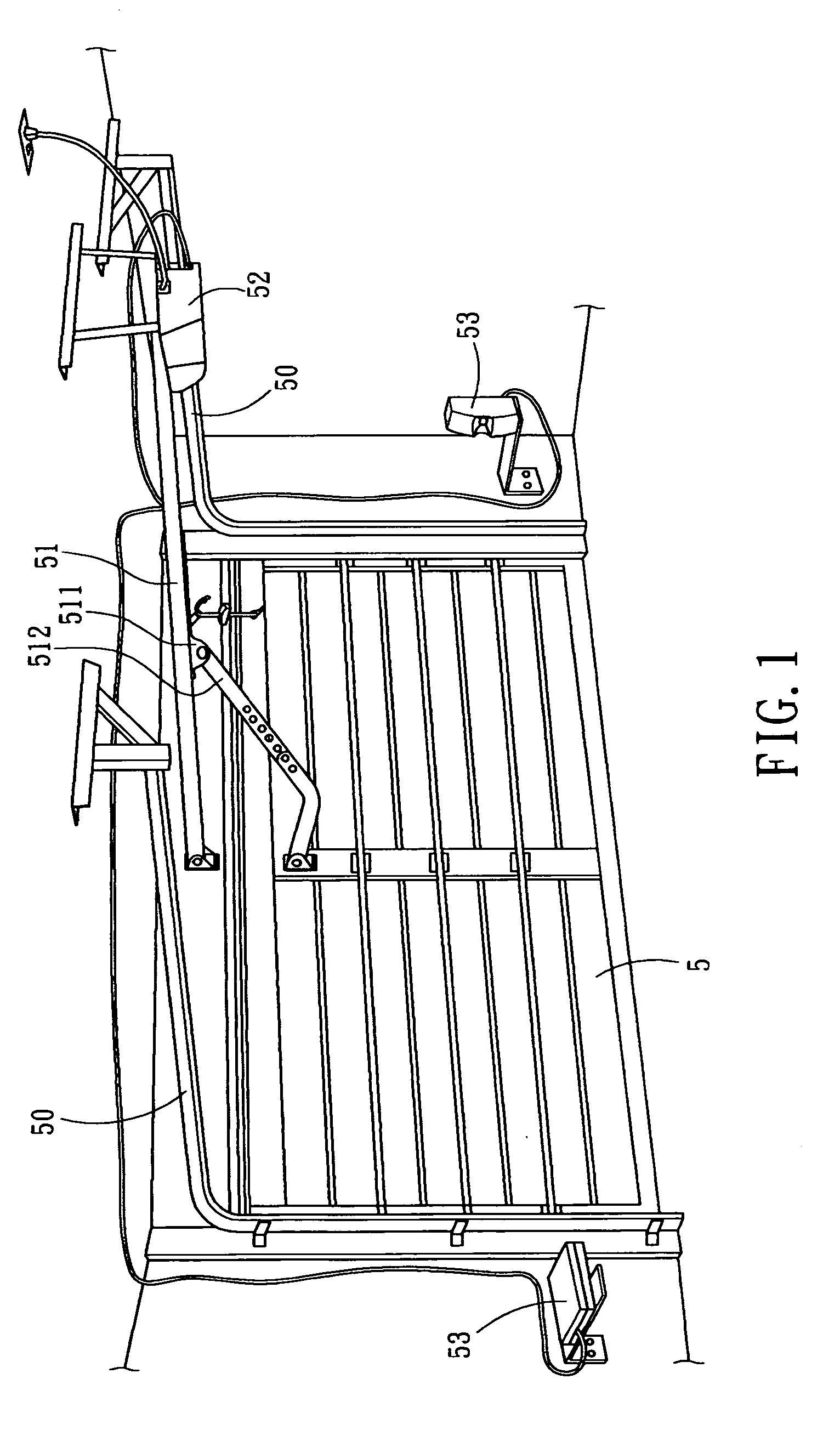
RELATED APPLICATIONS This application is a continuation-in-part of U.S. patent application Ser. No. 10 / 752,693, filed on Jan. 8, 2004.BACKGROUND OF THE INVENTION [0001] The present invention relates to a safety device for garage door. More specifically, the present invention relates to a safety device that is built on an extensive sensing network that can assure the safety when a garage door is closing. [0002] Presently, it is very popular to use automated garage door. It has a high practical value because it satisfies the car driver with safety and convenience when a car is moving in and out of a garage. Please refer to FIG. 1 for conventional garage door structure. On each of the two sides of a garage door 5 there is a L-shape supporting frame 50, so the garage door 5 can slide along the frame 50 through the action of the pulleys on both sides. In the center of the top, there is a fixing rod 51, which has a garage door control mechanism 52 at one end. On the fixing rod 51 there is...

Claims


Application Information

Patent Timeline
IPC IPC(8): G06M7/00E05F15/00E05F15/16
CPCE05Y2600/45E05Y2900/106E05F2015/436E05F15/668E05F2015/435E05F15/43E05F15/681G05B9/02G06M7/00
Inventor CHEN, DUKE
Owner EQUUS
Learn More