Eureka AIR delivers breakthrough ideas for toughest innovation challenges, trusted by R&D personnel around the world.

Combustion-powered, fastener-driving tool generating sparks in succession when triggered

a fastener and spark plug technology, applied in the direction of manufacturing tools, stapling tools, nailing tools, etc., can solve the problems of inability to reliably ignite the mixture, the spark plug cannot reliably ignite the gas concentration outside the gas concentration band, etc., to achieve reliable sparks, increase the possibility of ignition, and expand the gas concentration range

Inactive Publication Date: 2006-03-30
HITACHI KOKI CO LTD
View PDF17 Cites 25 Cited by
  • Summary
  • Abstract
  • Description
  • Claims
  • Application Information

AI Technical Summary

Benefits of technology

[0010] In view of the foregoing, it is an object of the present invention to provide a combustion-powered, fastener-driving tool capable of producing reliable sparks by preventing this flameout phenomenon and increasing the opportunities of ignition by expanding the gas concentration range in which the fuel can be stably ignited or burned.
[0018] Since the combustion-powered, fastener-driving tool of the present invention generates a plurality of sparks in the spark plug when the trigger is operated, the combustion-powered, fastener-driving tool can expand the gas concentration range, that is, the gas concentration band at which a reliable ignition ratio is obtained. Accordingly, stable ignition or combustion can be achieved at low temperatures or high temperatures.
[0019] By reducing the number of generated sparks based on the temperature, or varying the amount of consumed energy required for generating sparks, based on the number of sparks to be generated, the combustion-powered, fastener-driving tool of the present invention can reduce unnecessary power consumption in the battery, which is mounted in the combustion-powered, fastener-driving tool.

Problems solved by technology

However, a spark from the spark plug cannot reliably ignite a gas concentration outside of the gas concentration band, that is, when the ignition ratio is less than 100%.
Such changes in the amount of liquid gas injected at a low temperature or a high temperature may result in a gas concentration outside of the gas concentration band, making it impossible to ignite the mixture reliably.
This unreliable ignition is likely due primarily to a flameout phenomenon in which the electrode of the spark plug robs the heat from the spark.

Method used


Image

  • Combustion-powered, fastener-driving tool generating sparks in succession when triggered
  • Combustion-powered, fastener-driving tool generating sparks in succession when triggered
  • Combustion-powered, fastener-driving tool generating sparks in succession when triggered

Examples


Embodiment Construction

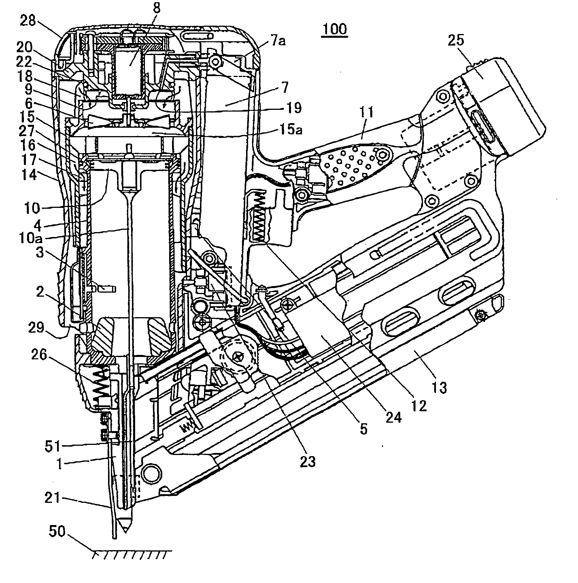
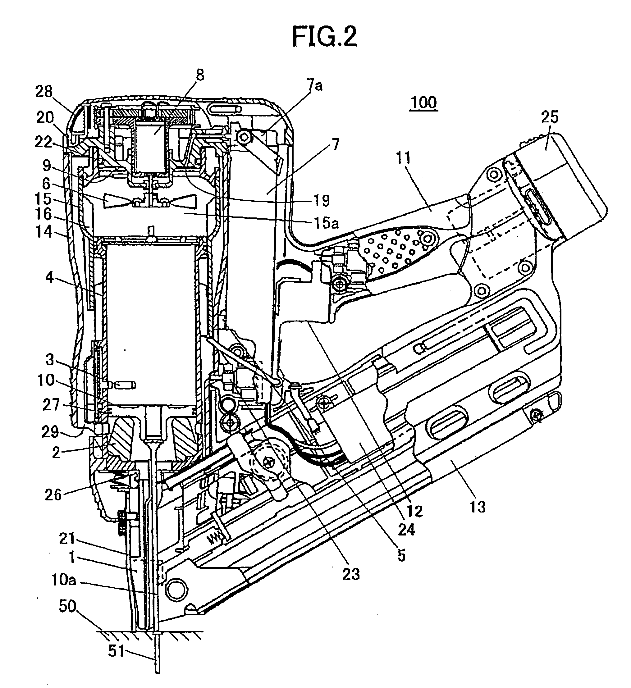
[0031] A combustion-powered, fastener-driving tool according to a preferred embodiment of the invention will be described with reference to the accompanying drawings. Hereinafter, the terms “upward”, “downward”, “upper”, “lower”, “above”, “below”, “beneath” and the like will be used throughout the description assuming that the combustion-powered, fastener-driving tool is disposed in an orientation in which it is used as shown in FIGS. 1 and 2.

[0032]FIGS. 1 and 2 are cross-sectional views showing a combustion-powered, fastener-driving tool 100, and particularly a nail-driving tool. FIG. 1 shows the fastener-driving tool 100 when a piston 10 is positioned in an initial states while FIG. 2 shows the combustion-powered, fastener-driving tool when the piston 10 is in a bottom dead center. The components and operations of the nail-driving tool are described below with reference to FIGS. 1 and 2.

[0033] As shown in FIG. 1, the fastener-driving tool 100 includes a housing 14 that forms a f...


PUM

PropertyMeasurementUnit
temperatureaaaaaaaaaa
voltageaaaaaaaaaa
voltageaaaaaaaaaa

Abstract

A combustion-powered, fastener-driving tool includes a cylinder and a combustion chamber disposed on top of the cylinder that accommodates a gaseous mixture of existing air in the combustion chamber and fuel injected therein. A spark plug generates a spark to combust the gaseous mixture in the combustion chamber. A trigger produces the spark in the spark plug when operated. A piston is movably supported in the cylinder and driven by combustion in the combustion chamber. A driving blade is coupled to the piston for driving a fastener. A spark controller is provided for generating a plurality of sparks in succession with the spark plug.

Description

BACKGROUND OF THE INVENTION [0001] 1. Field of the Invention [0002] The present invention relates to a combustion-powered, fastener-driving tool for driving fasteners, such as nails, rivets, or staples. The combustion-powered, fastener-driving tool includes a cylinder in the top section of which is formed a combustion chamber. The combustion-powered, fastener-driving tool generates a motive force for driving a piston in the cylinder by igniting a mixture of air and a flammable gas in the combustion chamber. [0003] 2. Description of the Related Art [0004] Conventional combustion-powered, fastener-driving tools is disclosed, for example, in U.S. Pat. Nos. 5,197,646 and 4,522,162. Such conventional combustion-powered, fastener-driving tools typically include a housing serving as the main enclosure of the tool, a cylinder accommodated in the housing, a piston disposed in the cylinder and guided by the cylinder to move vertically in a reciprocating motion, a driving blade fixed to the pi...

Claims


Application Information

Patent Timeline
Patent Type & Authority Applications(United States)
IPC IPC(8): B25C1/14B25C1/08
CPCB25C1/08F02B5/00F02B63/02F02B77/08
Inventor FUJISAWA, HARUHISAAKIBA, YOSHITAKATAKANO, NOBUHIROISHIMARU, KENRONISHIKAWA, TOMOMASA
Owner HITACHI KOKI CO LTD
Why Eureka
Eureka Blog
Learn More