
Capsule filling machine

a filling machine and capsule technology, applied in the field of capsule filling machines, can solve the problem that the pin cannot exert sufficient pick up force on the micro-tablet, and achieve the effect of high precision dosing and production speed

Inactive Publication Date: 2006-03-30
IMA IND MASCH AUTOMATICHE SPA
View PDF6 Cites 9 Cited by
  • Summary
  • Abstract
  • Description
  • Claims
  • Application Information

AI Technical Summary

Benefits of technology

[0010] In particular, the aim of the present invention is to produce a capsule filling machine which guarantees high precision dosing.
[0011] Another aim of the present invention is to propose a capsule filling machine which, together with the above-mentioned precision dosing, continues to guarantee the reliability, productivity and safety levels required of such machines, as well as the production speed typical of current capsule filling machine, in particular of high productivity continuous-motion capsule filling machines.

Problems solved by technology

Whilst the piston can pick up precise and constant volumes of powdered pharmaceutical material in the hollow cylinder, in the case of micro-tablets, the piston cannot exert sufficient pick up force on the micro-tablets to guarantee a given and constant number of micro-tablets which will then be released into each capsule body.

Method used


Image

  • Capsule filling machine
  • Capsule filling machine
  • Capsule filling machine

Examples


Embodiment Construction

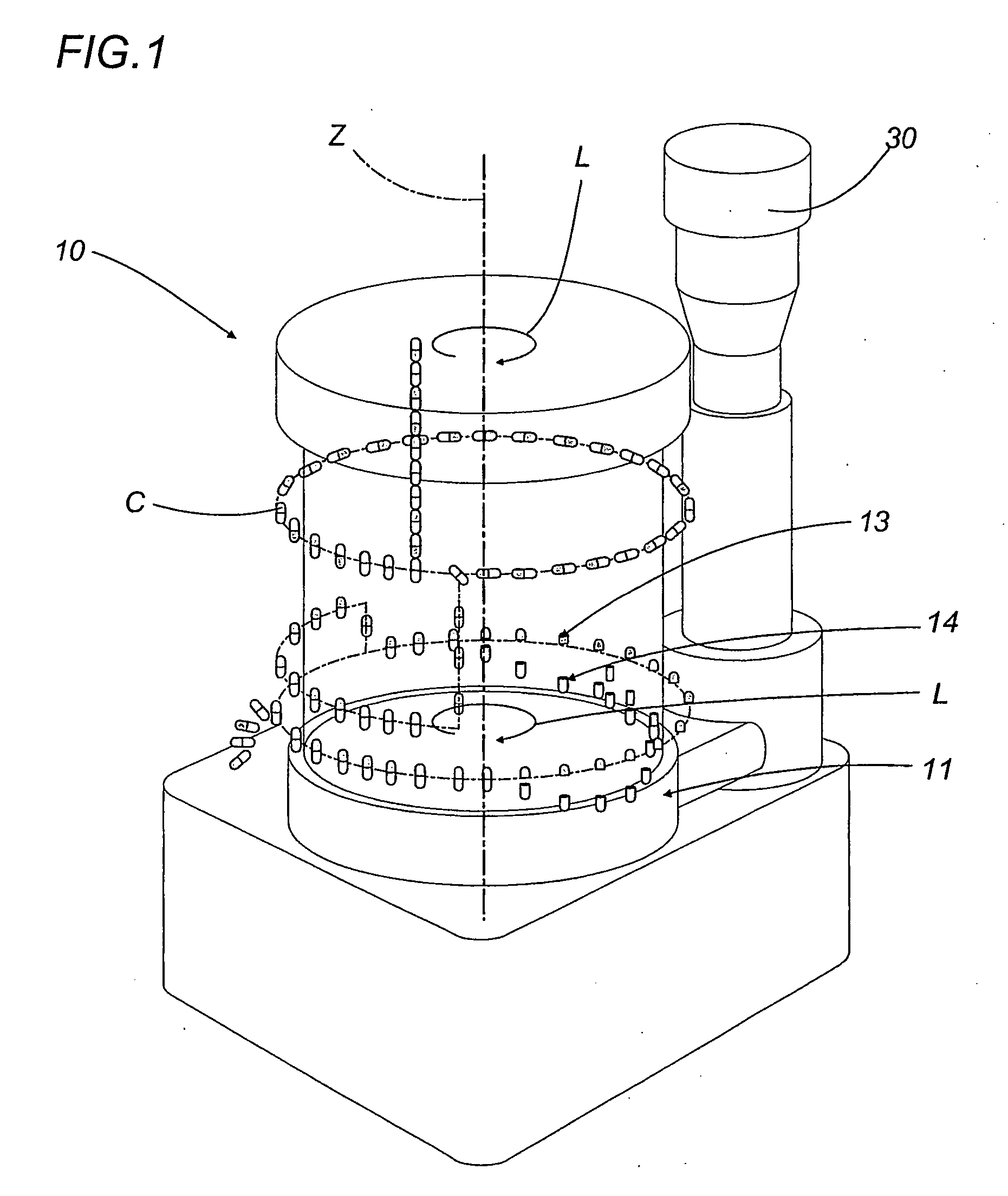
[0019] With reference to FIG. 1, the capsule filling machine disclosed, labelled 10 as a whole, is used for filling capsules C of the known type with a capsule lid and a capsule body, labelled 13 and 14 respectively, with given quantities of particles 12 of pharmaceutical material, specifically pharmaceutical micro-tables 12 or pellets.

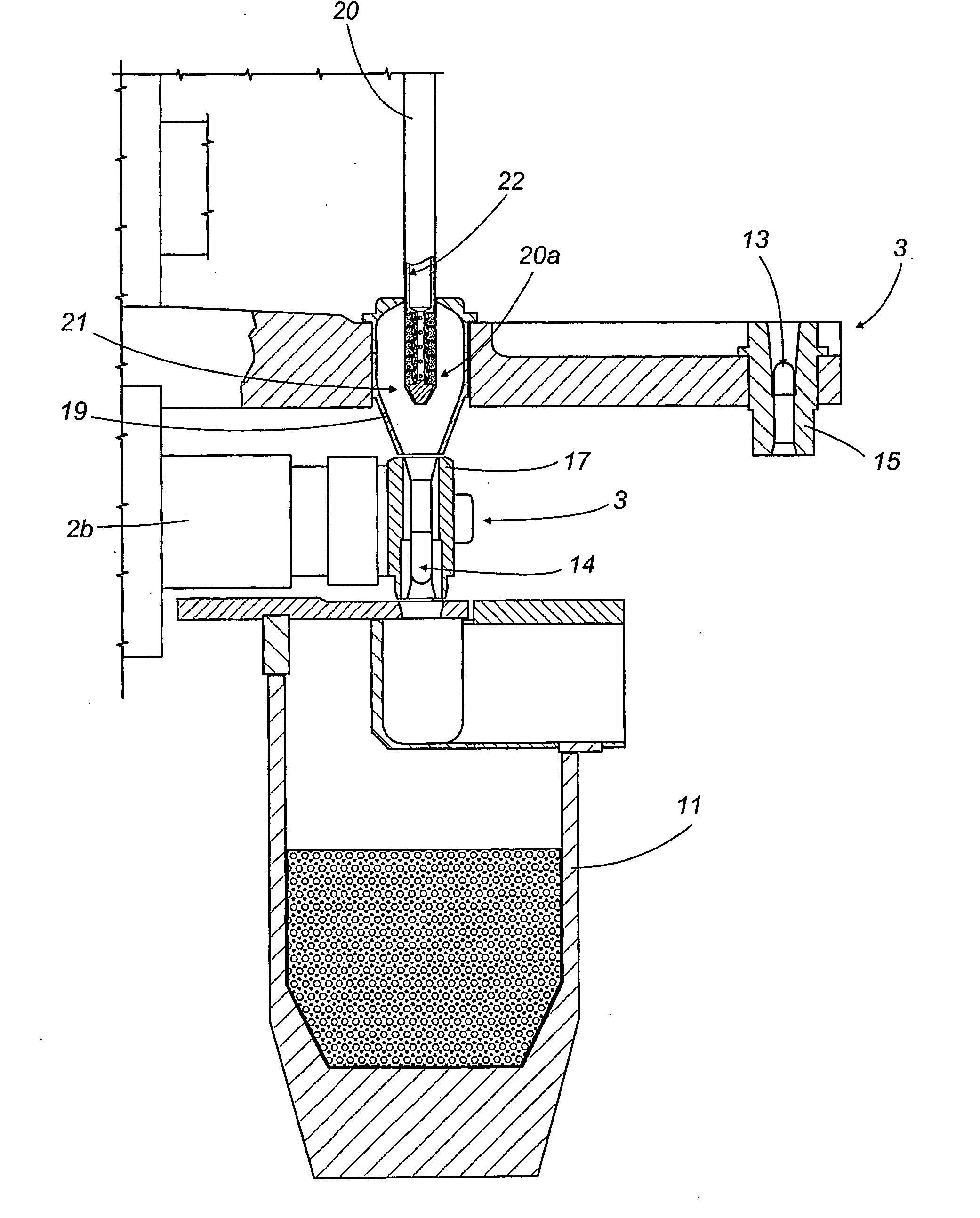
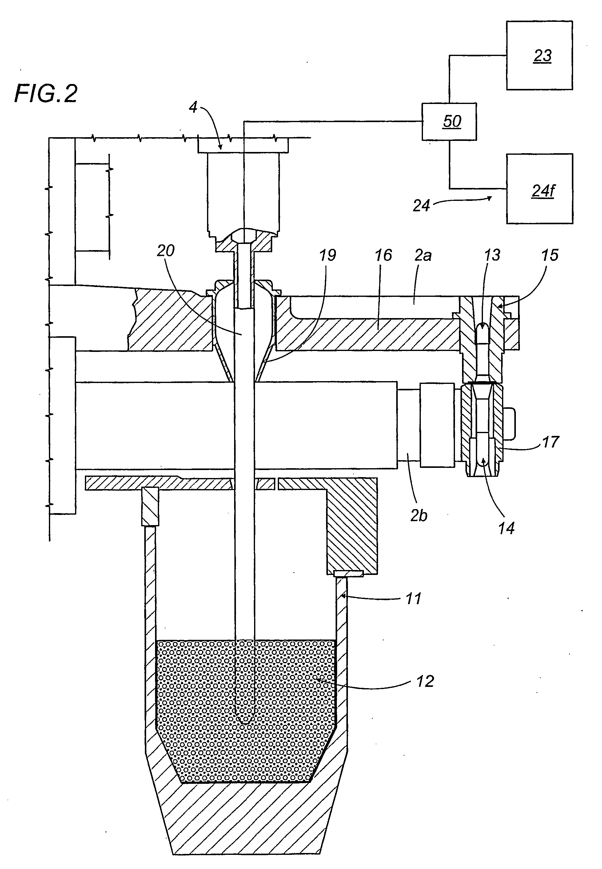
[0020] As illustrated in FIGS. 1, 2 and 3, the capsule filling machine 10 comprises a first carrousel 2 rotating about a vertical axis Z in the direction indicated by the arrow L and having radial arms 2a, 2b supporting a plurality of slide units 3 for picking up capsule bodies 14 of capsules C and moving them in a horizontal direction, and a tank 11 with a known, substantially toroidal shape, located at the base of the capsule filling machine 10 and designed to hold a mass of micro-tablets 12 supplied from a feed hopper 30.

[0021] The machine 10 also comprises a second carrousel 4 (FIG. 2), also rotating about the vertical axis Z, again in the direc...


PUM

PropertyMeasurementUnit
Angleaaaaaaaaaa
Flow rateaaaaaaaaaa

Abstract

A capsule filling machine (10) for the production of hard gelatin capsules (C) of the type with a capsule lid and a capsule body (13, 14) containing pharmaceutical micro-tablets (12) comprises a first rotary carrousel (2) supporting a plurality of slide units (3) for picking up and handling capsules (C) in order to open then close the capsules (C) by separating then joining the capsule lids (13) and the capsule bodies (14); a second carrousel (4), which rotates in such a way that it is synchronized with the first carousel (2), having a plurality of reciprocating doser means (21) moving between a first operating position in which the doser means (21) are designed to pick up particulate material (12) from a tank (11) containing the material which is attached to the machine (10) and a second operating position in which they release the material into the capsule (C) bodies (14). The doser means (21) each comprise a hollow nozzle (22) with a plurality of seats (25) on its edge for picking up and holding the particulate pharmaceutical material (12), each seat (25) communicating with pneumatic means (24,24a,24b), the pneumatic means (24,24a,24b) comprising pneumatic vacuum means (24a) which, in the first operating position, suck up and hold individual particles (12) of the material in respective seats (25) of the nozzle (22), and pressurised pneumatic means (24b) which generate a flow that discharges the particles (12) from the seats (25) in the second operating position to release the material into the capsule (C) bodies (14).

Description

TECHNICAL FIELD [0001] The present invention relates to a capsule filling machine for the production of hard gelatin capsules containing pharmaceutical material. [0002] In particular, the pharmaceutical material in the hard gelatin capsules of the type with a capsule lid and a capsule body to which the present invention advantageously refers is in the form of particles, that is to say, micro-tablets or pellets. BACKGROUND ART [0003] Generally speaking, a capsule filling machine of the known type currently used basically comprises a central turret or carrousel rotating with discontinuous or stepping motion and equipped with a plurality of operating units located along the edge of the turret and driven by the turret by means of reciprocating drive parts. [0004] Each operating unit on the turret comprises a slide supporting element for holding one or more capsules to be carried to a plurality of work stations in which successive operating steps take place, in accordance with a known me...

Claims


Application Information

Patent Timeline
IPC IPC(8): B65B47/00A61J3/07A61K9/48A61K47/42B65B35/06B65B37/16
CPCA61J3/074B65B37/16B65B35/06B65B37/14
Inventor TREBBI, ROBERTZERBINATI, ENRICO
Owner IMA IND MASCH AUTOMATICHE SPA
Learn More