
Shock-absorbing joint and spine replacements

a spine and joint technology, applied in the field of prosthetic discs and joint replacement components, can solve the problems of reduced disc degeneration, reduced disc degeneration, and reduced disc degeneration rate, and achieve the effect of reducing the number of surgical treatments, and reducing the number of surgical procedures

Inactive Publication Date: 2006-03-23
FERREE BRETA
View PDF4 Cites 187 Cited by
  • Summary
  • Abstract
  • Description
  • Claims
  • Application Information

AI Technical Summary

Benefits of technology

"The invention is about improving prosthetic implants for replacing damaged spine and joints. The problem is that current procedures for replacing these components remove the degenerated disc, which can lead to further degeneration of adjacent discs. The invention proposes the use of shock absorbers, cushioning mechanisms, and other improvements in the way prosthetic components are incorporated into the disc space and materials to ensure strength and longevity. The invention also includes the use of fluids and cells to dampen loads and promote healing. The technical effects of the invention include reducing pain, preserving disc function, and improving the longevity of prosthetic implants."

Problems solved by technology

The nucleus becomes thinner and less able to handle compression loads.
The redundant annular fibers are less effective in controlling vertebral motion.
Current surgical treatments of disc degeneration are destructive.
These destructive procedures lead to acceleration of disc degeneration.
The first two groups of procedures compromise the treated disc.
The additional stress results in premature disc degeneration of the adjacent discs.
These compressive stresses can eventually cause painful fractures and can often result in the implant loosening after several years.

Method used


Image

  • Shock-absorbing joint and spine replacements
  • Shock-absorbing joint and spine replacements
  • Shock-absorbing joint and spine replacements

Examples


Embodiment Construction

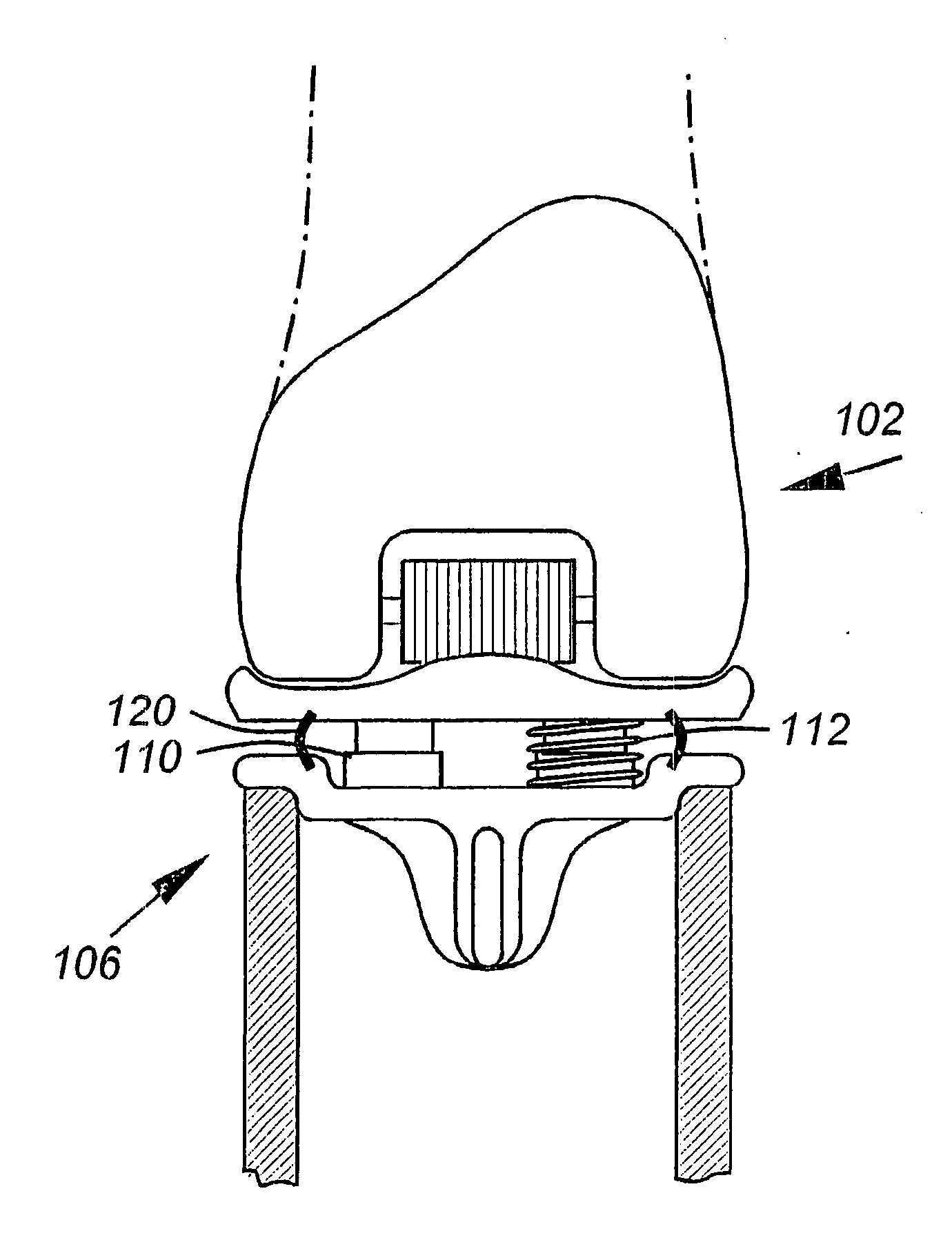
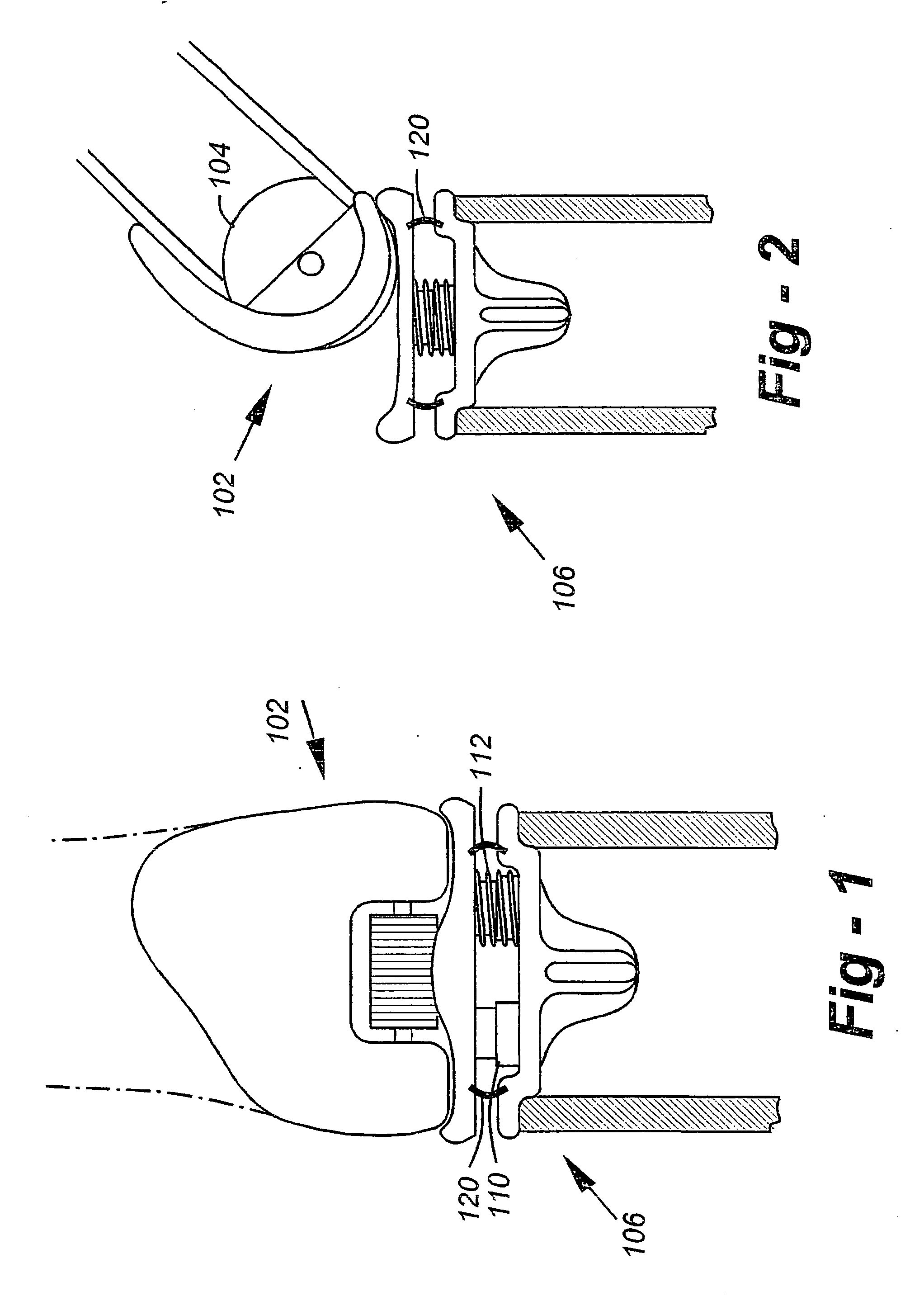
[0074] This invention is broadly directed to spine and joint-replacement components wherein, in preferred embodiments, at least a portion of the respective implant contains a cushioning or shock-absorbing member. FIG. 1 is an anterior view of a total knee replacement (TKR) according to the invention. FIG. 2 is a lateral view of the TKR of FIG. 1. The femoral component, 102, includes a wheel 104. The tibial component, 106, includes one or more shock-absorbing components, such as piston assembly 110 and one or more springs such as 112 which may be separate from or surround each piston assembly. The spring on the left in FIG. 1 was not drawn to better illustrate the cylinder halves. An optional membrane 120 may surround the tibial shock absorbers to hold in fluid and / or particulates such as metal debris. The natural synovial fluid within the knee joint may be used to advantage to cooperate with the dampening mechanism.

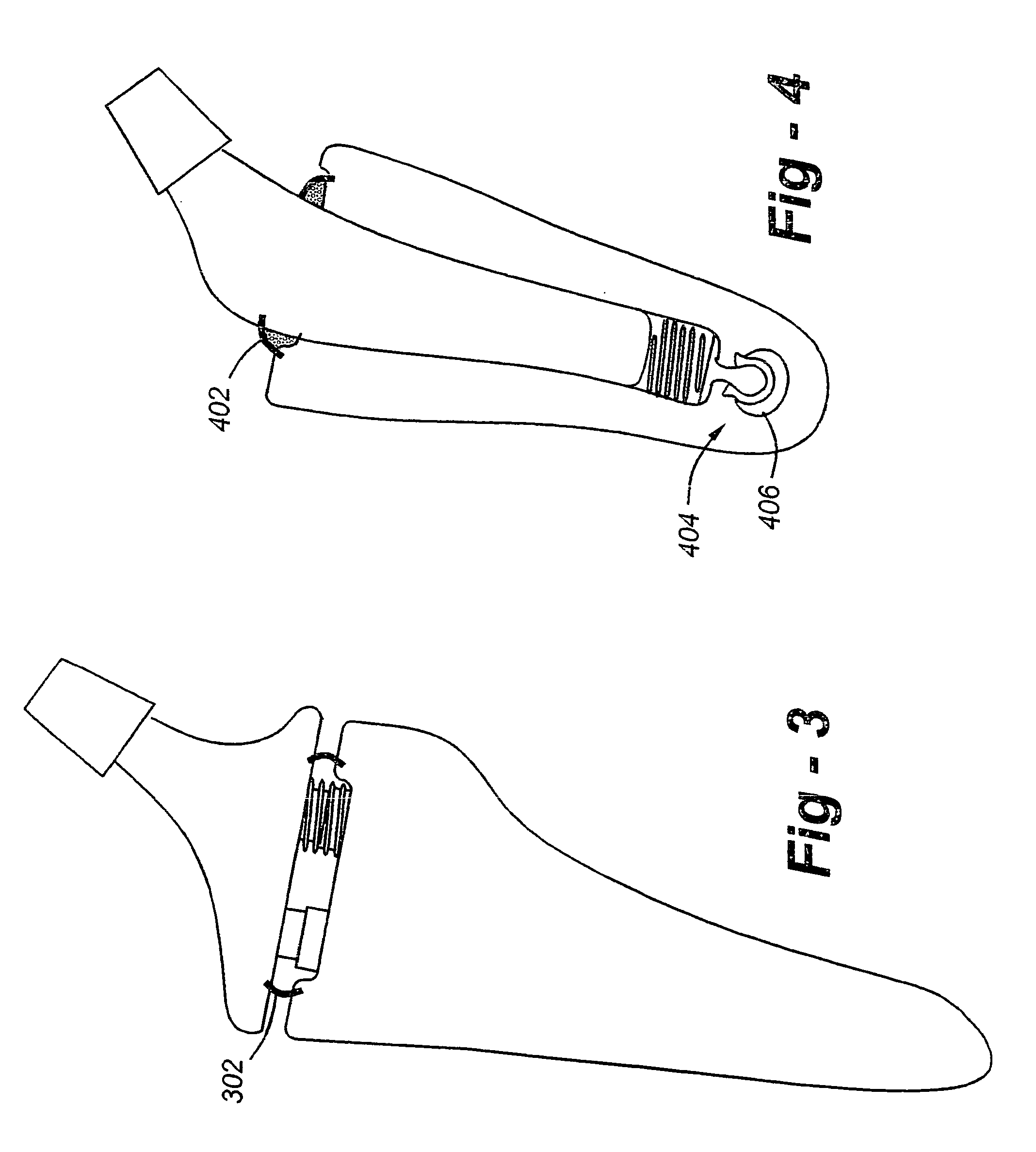
[0075]FIG. 3 is a total hip (THR) embodiment of the invention. As w...


PUM

PropertyMeasurementUnit
sizeaaaaaaaaaa
pressureaaaaaaaaaa
weightaaaaaaaaaa

Abstract

Numerous joint replacement implant embodiments including a total knee replacement implant including a femoral component (102) having a wheel (104); and a tibial component (106) including a shock-adsorbing component with a piston assembly (110) and spring (112). Said implants contain a cushioning or shock-absorbing member to dampen axial loads and other forces. In many embodiments, fluid is force rapidly from the device wherein compression and dampening is achieved by valves or other pathways that allow for a slower return of the fluid back into the implant as the pressure is relieved.

Description

FIELD OF THE INVENTION [0001] This invention relates generally to prosthetic implants and, more particularly, to artificial disc and joint replacement components incorporating shock absorbers, cushioning mechanisms, and other improvements. BACKGROUND OF THE INVENTION [0002] Premature or accelerated disc degeneration is known as degenerative disc disease. A large portion of patients suffering from chronic low back pain are thought to have this condition. As the disc degenerates, the nucleus and annulus functions are compromised. The nucleus becomes thinner and less able to handle compression loads. The annulus fibers become redundant as the nucleus shrinks. The redundant annular fibers are less effective in controlling vertebral motion. The disc pathology can result in: 1) bulging of the annulus into the spinal cord or nerves; 2) narrowing of the space between the vertebra where the nerves exit; 3) tears of the annulus as abnormal loads are transmitted to the annulus and the annulus ...

Claims


Application Information

Patent Timeline
Patent Type & Authority Applications(United States)
IPC IPC(8): A61F2/32A61F2/30A61F2/44A61F2/38A61F2/36A61B17/80A61B17/86A61F2/00A61F2/34
CPCA61F2002/485A61F2002/3652A61F2220/0033A61F2220/0041A61F2230/0006A61B17/80A61B17/86A61F2/30742A61F2/30942A61F2/32A61F2/3609A61F2/3662A61F2/367A61F2/3676A61F2/38A61F2/3859A61F2/389A61F2/441A61F2/442A61F2/4425A61F2002/30123A61F2002/30332A61F2002/30354A61F2002/30367A61F2002/30372A61F2002/30446A61F2002/30505A61F2002/30563A61F2002/30566A61F2002/30568A61F2002/30578A61F2002/30579A61F2002/30581A61F2002/30589A61F2002/30591A61F2002/30601A61F2002/30604A61F2002/30624A61F2002/3064A61F2002/30665A61F2002/30673A61F2002/30683A61F2002/3233A61F2002/3412A61F2002/3611A61F2002/3625A61F2002/365A61F2220/0025A61F2002/30433A61F2002/30639A61F2/484
Inventor FERREE, BRETA
Owner FERREE BRETA
Learn More