
Asymmetric HRTF/ITD storage for 3D sound positioning

a technology of asymmetric storage and 3d sound, applied in the field of sound processing, can solve the problems of large memory requirements, affecting the design, and not providing as many distinct positions, and achieve the effect of reducing the requirements of head related transfer function (hrtf) storag

Active Publication Date: 2006-03-23
AVAGO TECH INT SALES PTE LTD
View PDF5 Cites 18 Cited by
  • Summary
  • Abstract
  • Description
  • Claims
  • Application Information

AI Technical Summary

Benefits of technology

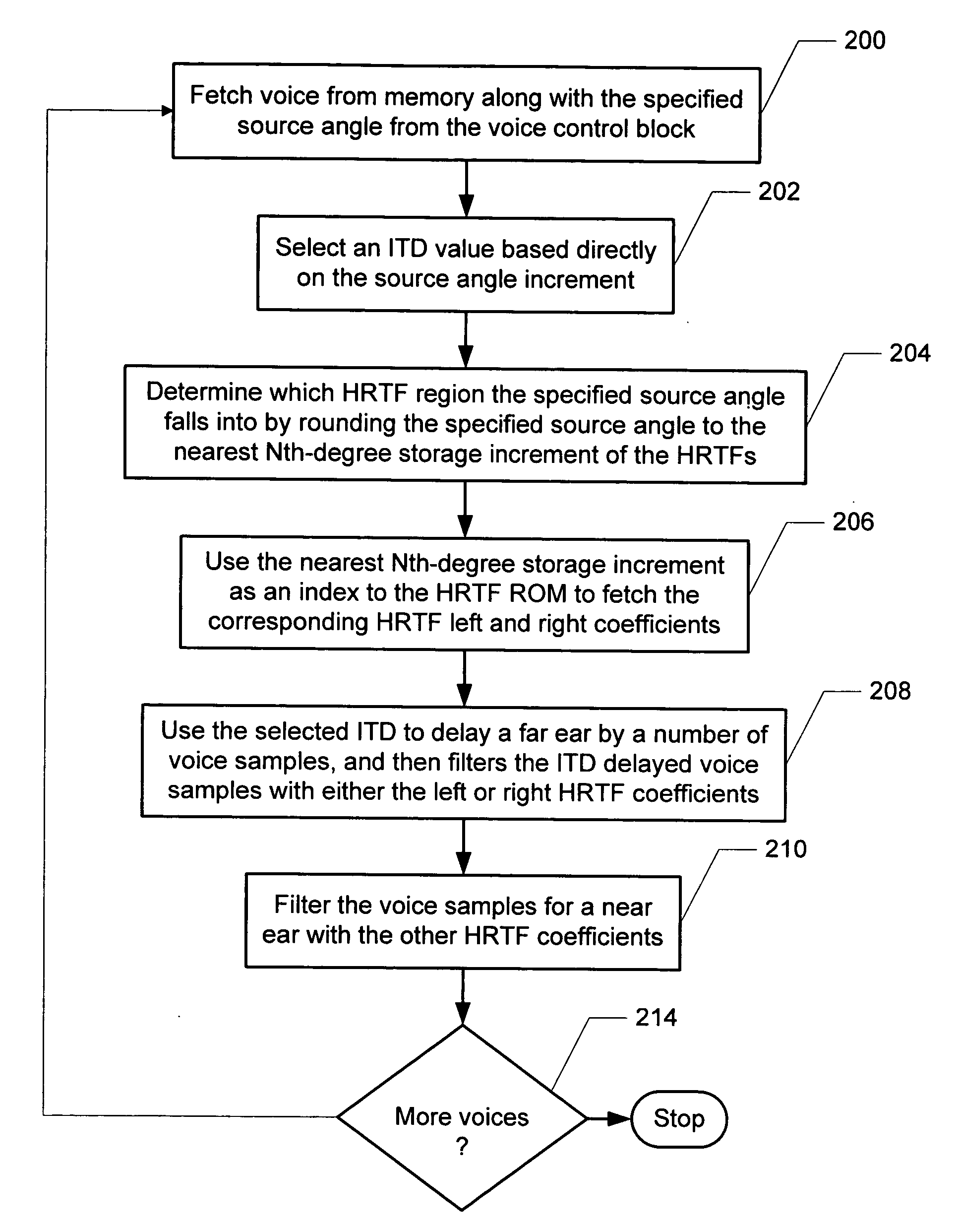
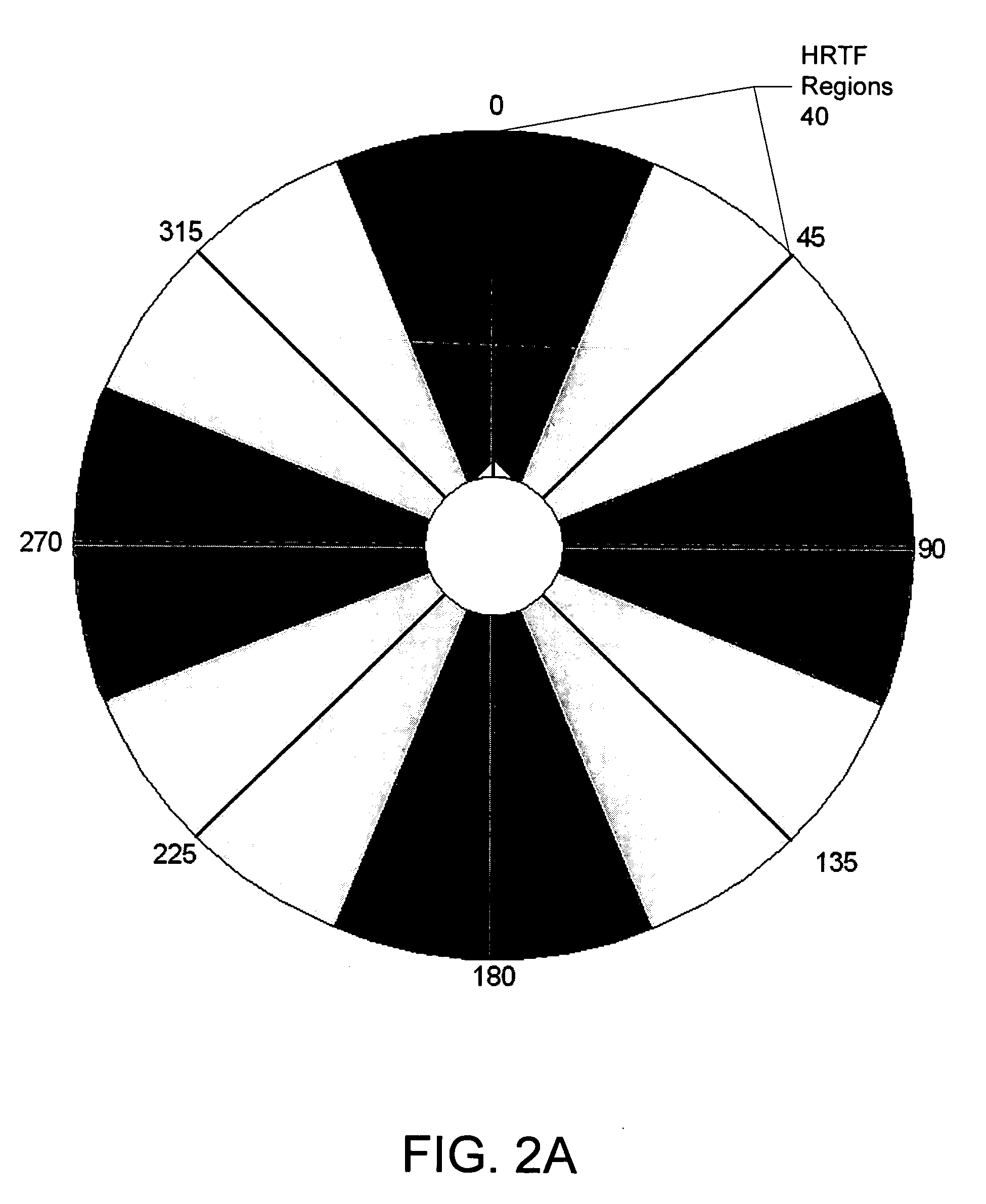
[0011] The present invention provides a method and system for reducing head related transfer function (HRTF) storage requirements for 3-D sound processing of an input sound having a specified source angle increment. According to the present invention, interaural time difference (ITD) values are selected based directly on the source angle increment, while HRTFs for processing the input sound are stored in angle increments larger than the source angle increment.
[0012] According to the method and system disclosed herein, ITD values are still used based on the source angle increment, but because the set of left and right HRTF coefficients do not have to be stored for every source angle increment, the present invention effectively reduces HRTF storage requirements. For a sound that is stationary at the same angle for many samples, this also reduces the number of accesses to memory. This invention will further reduce the number of required memory accesses of even a moving 3D sound, potentially providing a considerable savings in power dissipation. Asymmetrical HRTF / ITD storage offers several benefits for low-power, low-cost 3D sound solutions, while making a small compromise in quality.

Problems solved by technology

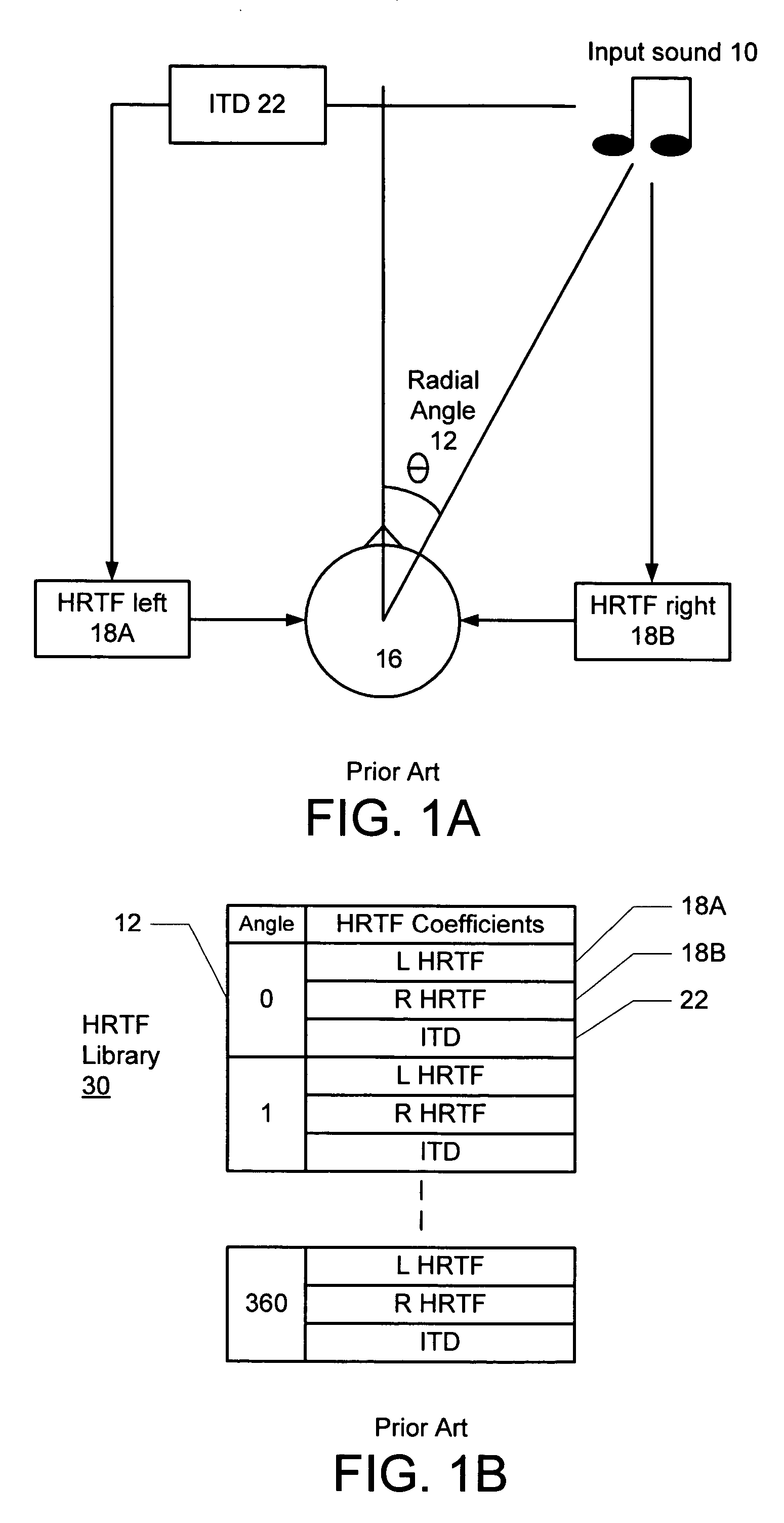
A problem with implementing 3D sound positioning in hardware is the large memory requirements for storing the filter coefficients of the HRTFs 18 for every angle 12 that is needed.
If elevational positioning is also implemented or if higher order filters are used, these storage requirements may quickly become a burden on the design.
The tradeoff with such an implementation is not providing as many distinct positions to place the 3D sound.
For a moving object that passes through several successive angles, this would likely create jumpiness in the sound and, in the case when interpolative smoothing is not implemented, the sound will severely crackle.
This would likely create distorted magnitude responses for the interpolated HRTFs, and interpolating in the frequency domain with any degree of accuracy is much too costly.

Method used


Image

  • Asymmetric HRTF/ITD storage for 3D sound positioning
  • Asymmetric HRTF/ITD storage for 3D sound positioning
  • Asymmetric HRTF/ITD storage for 3D sound positioning

Examples


Embodiment Construction

[0019] The present invention relates to a method and system for reducing HRTF / ITD storage requirements for 3-D sound positioning. The following description is presented to enable one of ordinary skill in the art to make and use the invention and is provided in the context of a patent application and its requirements. Various modifications to the preferred embodiments and the generic principles and features described herein will be readily apparent to those skilled in the art. Thus, the present invention is not intended to be limited to the embodiments shown, but is to be accorded the widest scope consistent with the principles and features described herein.

[0020] Considering the ITD values 22 in some sound processors may be artificially inserted and represent a number of samples to delay the input sound to the contralateral ear by, the memory requirements for the ITD values 22 are almost negligible in comparison to the large amounts of data required for the HRTF coefficients.

[0021...


PUM


Abstract

A method and system for reducing head related transfer function (HRTF) storage requirements for 3-D sound processing of an input sound having a specified source angle increment is provided. Interaural time difference (ITD) values are selected based directly on the source angle increment; and HRTFs for processing the input sound are stored in angle increments larger than the source angle increment.

Description

FIELD OF THE INVENTION [0001] The present invention relates to sound processing, and more particularly to a method and system for asymmetrically storing HRTF / ITD measurement for 3-D sound positioning. BACKGROUND OF THE INVENTION [0002] To find the sound pressure that an arbitrary source x(t) produces at the ear drum, all that is required is the impulse response h(t) from the source to the ear drum. This is called the Head-Related Impulse Response (HRIR), and its Fourier transform H(f) is called the Head Related Transfer Function (HRTF). The HRTF models the sound filtering characteristics of the human pinna (projecting portion of the external ear) and torso (a human trunk) and captures all of the physical cues to the source localization. Once the HRTF for the left ear and the right ear are known, accurate binaural signals can be synthesized from a monaural source. Most HRTF measurements essentially reduce the HRTF to a function of a sound's azimuth, elevation and frequency. [0003]FIG...

Claims


Application Information

Patent Timeline
IPC IPC(8): H04R5/02H04R5/00
CPCH04S2420/01H04S3/00
Inventor SFERRAZZA, BEN
Owner AVAGO TECH INT SALES PTE LTD
Learn More