Color image display panel and driving method thereof

a technology of color image and display panel, which is applied in the direction of optics, instruments, static indicating devices, etc., can solve the problems of increasing process costs, reducing the opening ratio of pixels, and providing excessive information unnecessary for human vision, so as to facilitate the production of the second optical modulating layer, improve the opening ratio, and achieve sufficient bright/dark display resolving power.

Inactive Publication Date: 2006-03-23
CANON KK
View PDF11 Cites 51 Cited by
  • Summary
  • Abstract
  • Description
  • Claims
  • Application Information

AI Technical Summary

Benefits of technology

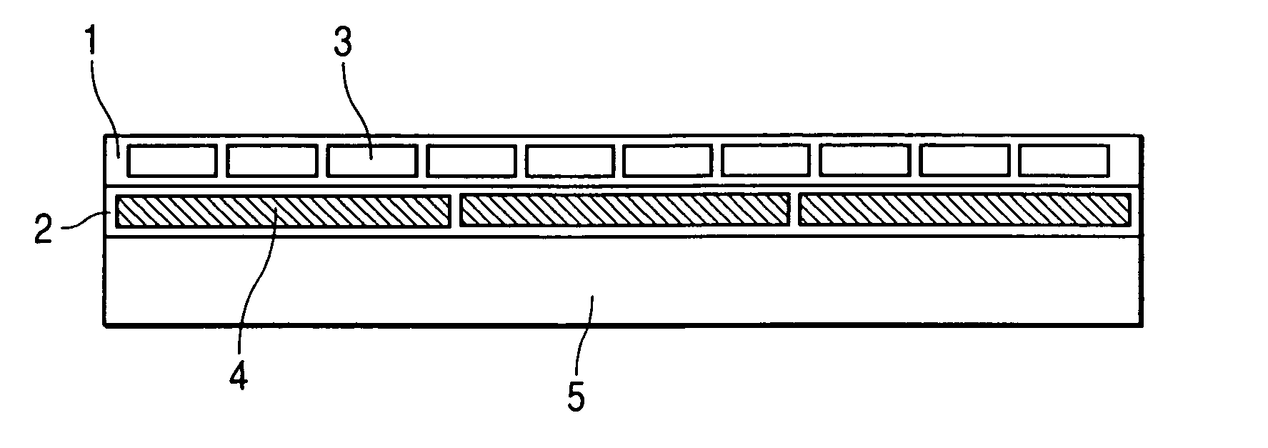
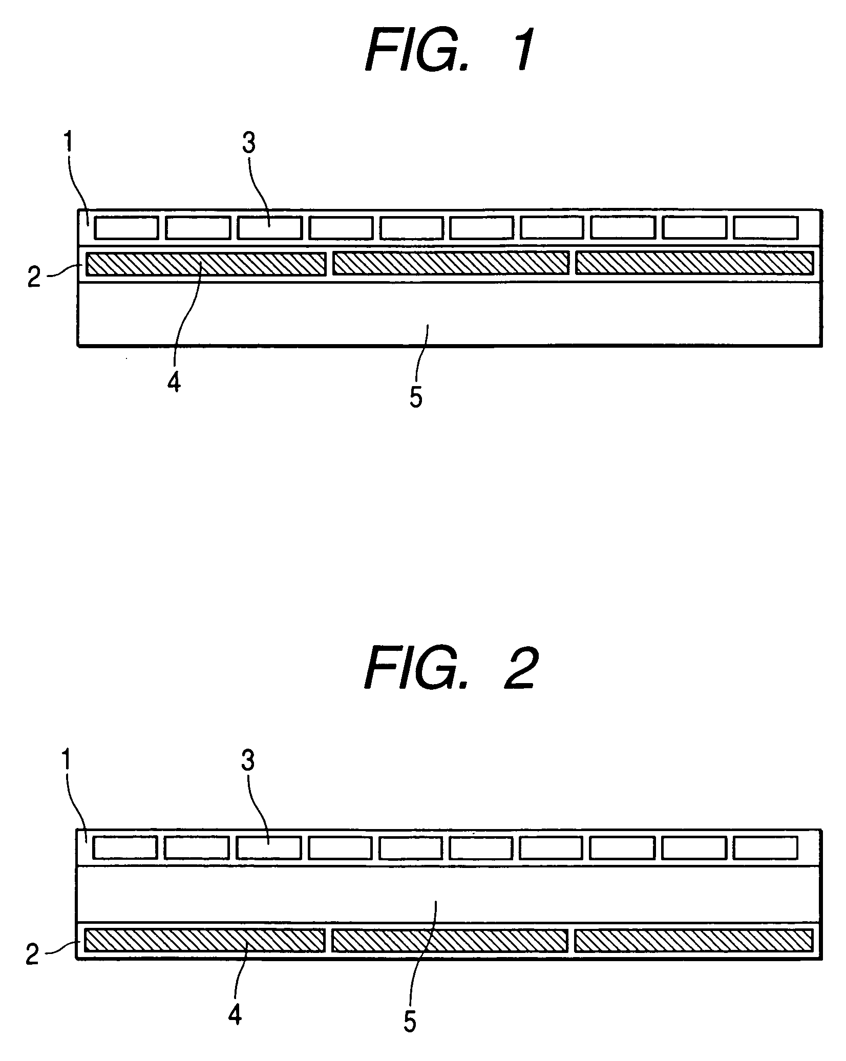
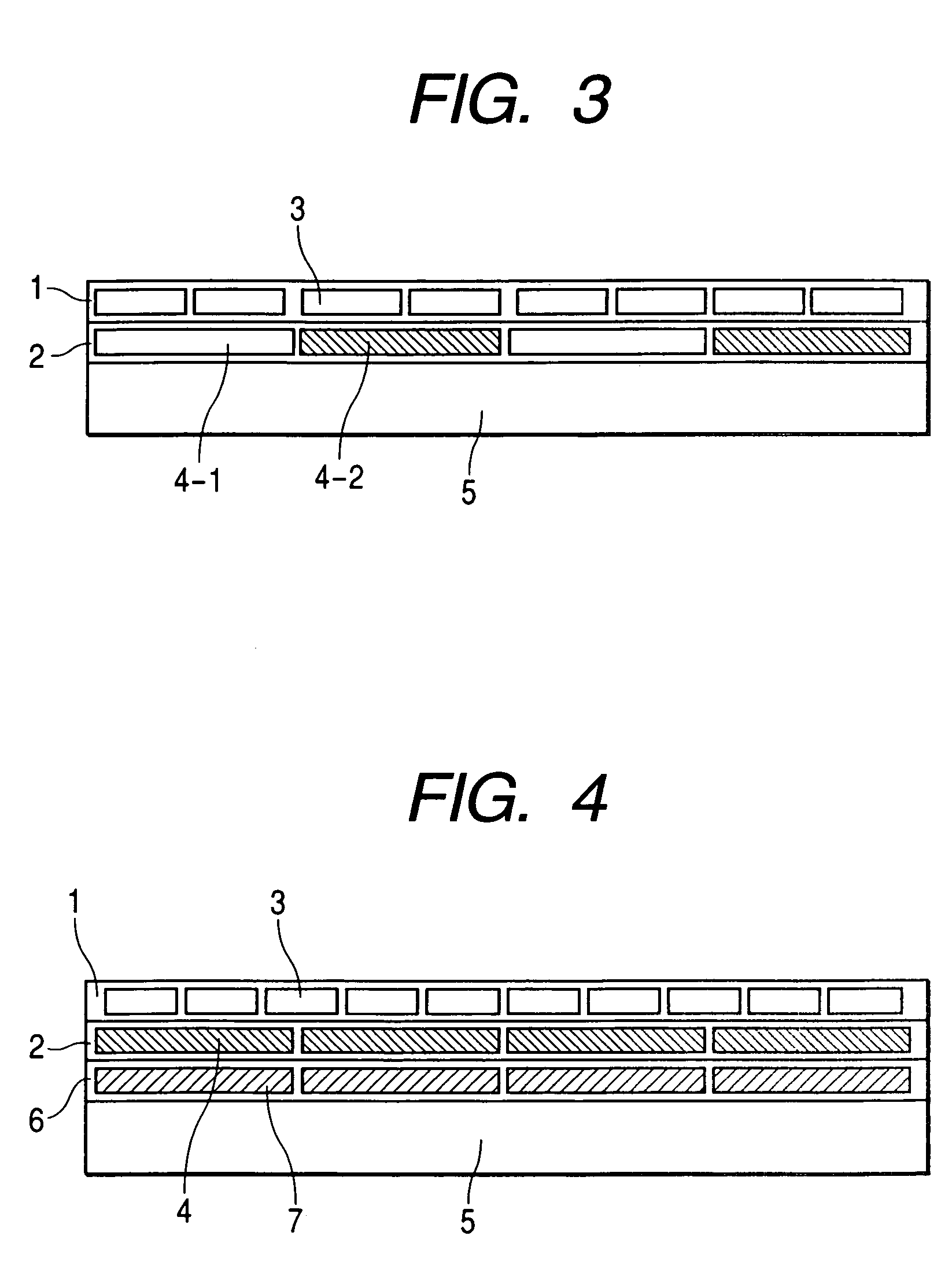
[0018] In the color image display panel of the invention of the aforementioned configuration, a desired color image can be displayed by a brightness control by the first light modulating layer and by a color hue control by the second light modulating layer. Since the first light modulating layer corresponding to the brightness observation in human vision has a smaller periodical structure in comparison with that in the second light modulating layer corresponding to the color hue observation, the color image display panel of the present invention has sufficient bright / dark display resolving power.
[0019] In comparison with the aforementioned bright / dark resolving power, the color display resolving power of the second light modulating layer is relatively lower, but matching the human visionary characteristics, it does not constitute a problem but helps to improve the opening ratio and to facilitate the production in the second optical modulating layer. Also such a feature that the second optical modulating layer has a larger repetition period than in the first layer also increases a tolerance for displacement in an alignment of the first layer and the second layer, thereby facilitating the production of the color image display panel.
[0020] The color image display panel of the present invention has many advantages as shown in the following. It can provide a brighter and sharper color display than in a color display panel of a one-layer structure. Also it can provide a high-definition display with respect to bright and dark levels. It has a sufficient display ability matching the human visionary characteristics. It can reduce a number of switch elements in pixel driving circuits. It is adapted for displaying an image of compressed data used for broadcasting and recording. Besides it has a margin in the working precision at the manufacture, thereby allowing to improve the production yield and to reduce the production cost.
[0021] The driving method for the image display panel of the present invention can provide a sharpness in color display and a high definition in bright / dark levels in human observation. Also it provides a margin in the working precision at the manufacture of the image display panel, thereby allowing to improve the production yield and to reduce the production cost of the image display panel.

Problems solved by technology

Such display not only provides excessive information unnecessary for the human vision, but also is associated with drawbacks of a decrease in a pixel opening ratio and an increase in the process cost, resulting from a finer structure of the subpixels and increased drive wirings therefor.
However, in case the size of the subpixel is increased, a pixel formed by an assembly of the subpixels becomes larger, so that the luminance information cannot be displayed with a sufficient resolving power.

Method used


Image

  • Color image display panel and driving method thereof
  • Color image display panel and driving method thereof
  • Color image display panel and driving method thereof

Examples


example 1

[0055] In the following, a specific example of the color image display panel of the present invention, having a configuration shown in FIG. 1, will be explained with reference to FIG. 6. It is to be noted that the present invention is not limited to such example.

[0056] A polyester film of a thickness of 200 μm was washed, and an aluminum layer was deposited thereon and was subjected to a photolithographic process to prepare drive electrodes 13 of a width of 330 μm, with a spacing of 10 μm. Their surface was covered with a two-liquid curable acrylic resin layer of 1 μm, and then an urethane resin layer, in which a titanium oxide white pigment was dispersed, was formed with a thickness of 8 μm to constitute a scattering reflection layer 14. Again the two-liquid curable acrylic resin layer was applied by 1 μm, and then an aluminum layer was deposited and subjected to a photolithographic process to form a stripe-shaped common electrode 12 of a width of 10 μm. Utilizing a photolithograp...

example 2

[0060]FIG. 8 is a functional block diagram of a paper display utilizing an electrophoretic display apparatus of the invention, and an equipment system utilizing such paper display.

[0061] The functional blocks are mainly divided into two, one being a paper display module 81 and the other being a paper display system module 82.

[0062] The paper display module 81 is constituted of a paper display element array 83, a driving backplane 84, a drive circuit(X) 85 and a drive circuit(Y) 86, and a panel controller (not shown) may be additionally provided for supplying the driving backplane 84 and the drive circuits 85, 86 with an electric power and signals. An interface module 87 may also serve as such panel controller. Also a temperature detecting element (not shown) such as a thermocouple or a thermistor may be provided for a temperature compensation control. Also the paper display module 81 may include a digitizer 88. Such digitizer can be of various types, such as an electromagnetic ind...


PUM

PropertyMeasurementUnit
widthaaaaaaaaaa
widthaaaaaaaaaa
thicknessaaaaaaaaaa

Abstract

An image display panel having, in a multilayer structure, a first and second light modulating layers each comprising a periodical planar arrangement of a plurality of light modulating elements for modulating a color or a brightness of an incident light in response to an input signal, wherein the arrangement period of the light modulating element in the first light modulating layer is smaller than the arrangement period of the light modulating element in the second light modulating layer.

Description

TECHNICAL FIELD [0001] The present invention relates to a color image display panel and a driving method thereof. More specifically, it relates to a color image display panel having a multilayer structure of a bright-dark modulation layer causing a transparent / opaque change, and a color modulation layer. BACKGROUND ART [0002] Among the image display panels, there are known a cathode ray tube (CRT), a plasma display panel (PDP), an electroluminescence panel (ELP) etc., utilizing a light-emitting material, and a liquid crystal display (LCD), a dynamic micromirror display (DLP), an electrophoretic display (EPD) etc., utilizing an optical switch element not emitting light. [0003] A high-definition color image display panel is generally constituted of an assembly of plural pixels arranged planarly in a matrix arrangement. Also each pixel is often constituted of subpixels for modulating three lights based on three primary colors of the human vision. [0004] In practice, the aforementioned ...

Claims


Application Information

Patent Timeline
Patent Type & Authority Applications(United States)
IPC IPC(8): G09G3/36G02F1/13G02F1/1347G02F1/167G09G3/34
CPCG02F1/1347G02F1/13475G09G3/2003G09G2380/02G09G3/36G09G3/3607G09G2300/023G09G3/344
Inventor YUASA, SATOSHI
Owner CANON KK
Why Eureka
Try Eureka