
System for controlling temperature of a secondary battery module

a secondary battery and temperature control technology, applied in the field of secondary batteries, can solve the problems of not considering geometric configuration, malfunction, and excessive and achieve the effects of reducing the size, actively responding, and efficient control of the temperature of the battery modul

Active Publication Date: 2006-03-23
SAMSUNG SDI CO LTD
View PDF13 Cites 101 Cited by
  • Summary
  • Abstract
  • Description
  • Claims
  • Application Information

AI Technical Summary

Benefits of technology

[0010] In accordance with the present invention a system for controlling temperature of a secondary battery module is provided which can efficiently control the temperature of the battery module, actively respond to the exterior environment even in an intense environment, and which can minimize the size by simplifying the structure.
[0012] In another aspect of the present invention, a system for controlling temperature of a secondary battery module according to another embodiment of the present invention includes: a housing receiving a unit battery, the housing having an inlet and an outlet; and a temperature controller controls temperature of the heat transfer medium flowing into the housing. Since the temperature of the cooling medium which flows into the housing can be properly controlled by the temperature controller, the temperature of the unit battery can be easily controlled.
[0018] In exemplary embodiments, a heat dissipation member can be connected to an inlet and the thermoelectric elements can be mounted on a heat dissipation member. The heat dissipation member may have a bottom plate where the thermoelectric element is attached, and plural fins mounted in the bottom plate being spaced apart at a predetermined distance. Accordingly, the cooling medium passing through the inlet can contact broader area due to the bottom plate and plural pins so that the heat energy from the thermoelectric element can be supplied more effectively.

Problems solved by technology

If the heat emission does not occur properly, the temperature of the battery module may excessively increase due to the heat generated from each unit battery, and accordingly, not only the battery module but also machines with the battery module, can malfunction.
However, when thermoelectric elements are applied to the battery module in the above conventional art, their geometric configuration has not been considered, and they have been simply mounted on some portion of the battery module.
Accordingly, the satisfactory cooling efficiency of the battery module has not yet been achieved.

Method used


Image

  • System for controlling temperature of a secondary battery module
  • System for controlling temperature of a secondary battery module
  • System for controlling temperature of a secondary battery module

Examples


first embodiment

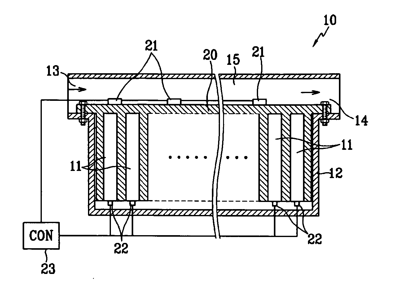
[0028]FIG. 1 is a schematic cross-sectional side view of a system for controlling the temperature of a secondary battery module (hereinafter “the system”) according to the present invention. The battery module 10 of the system includes multiple unit batteries 11, each having an electrode assembly having a positive plate, a negative plate, and a separator interposed between the positive plate and the negative plate to generate unit power, and a housing 12 receiving the unit batteries 11 which are spaced apart at a predetermined distance. Each of the unit batteries 11 of the present exemplary embodiment may be a lithium type secondary battery, such as a lithium-ion battery.

[0029] The housing 12 has an inlet 13 formed on one side thereof to allow air for controlling the temperature of the unit batteries 11 to flow in and an outlet 14 formed on the other side thereof to allow the air passing through the unit batteries 11 to flow out. An air duct 15 is formed between the inlet 13 and the...

second embodiment

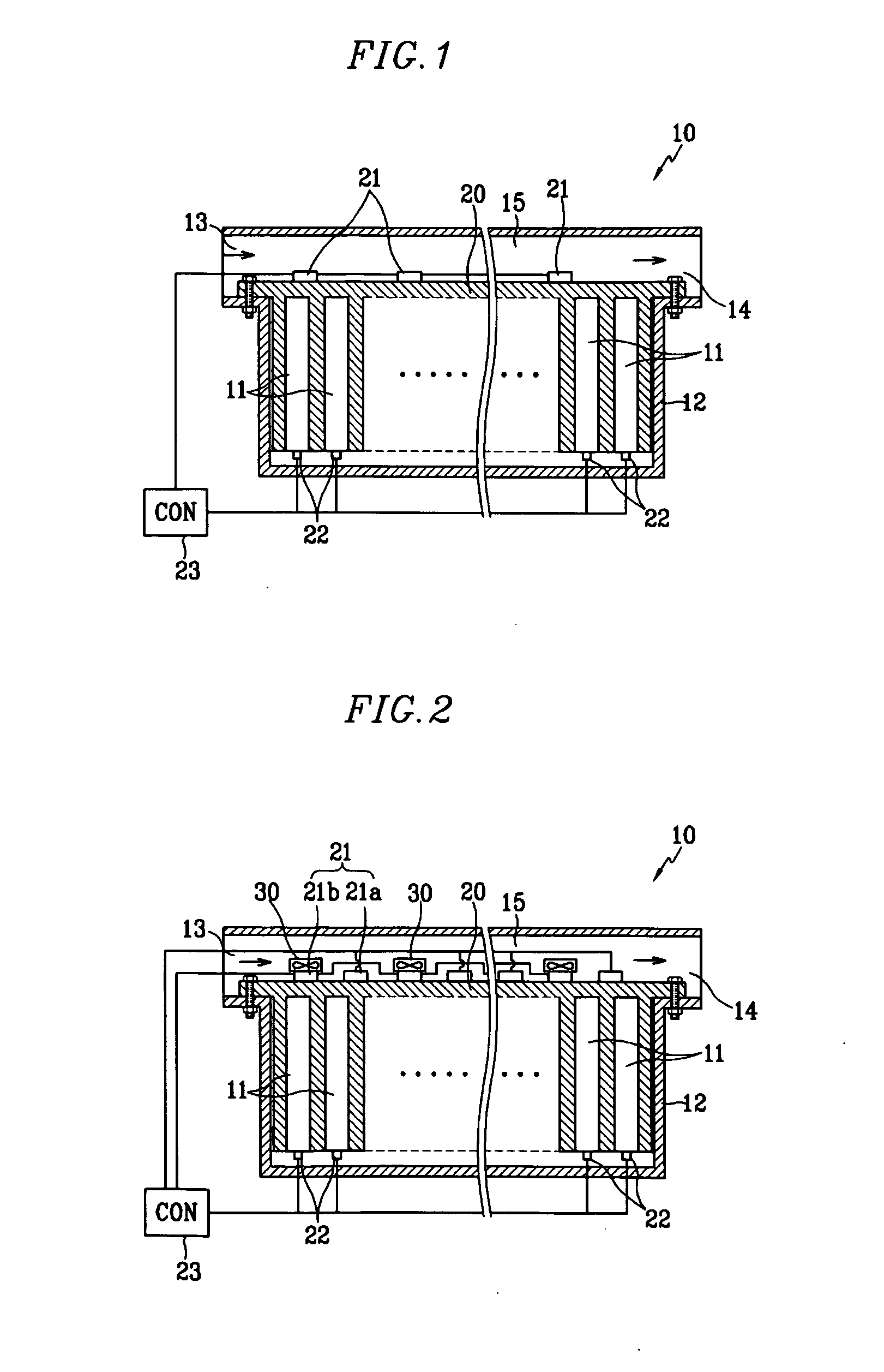
[0045] Now referring to FIG. 2, the present invention is described. In this exemplary embodiment, the thermoelectric elements 21 mounted on the heat sink 20 each have a thermoelectric heating element 21a for heating the heat sink 20 and a thermoelectric cooling element 21b for cooling the heat sink 20 which are separated mounted. That is, in this exemplary embodiment, the thermoelectric element for increasing the temperature of the unit batteries 11 and the thermoelectric element for cooling the temperature of the unit batteries 11 are separated for their respective heating and cooling purposes.

[0046] Such a structure can enhance the battery module lifetime which otherwise would be diminished by overwork of the thermoelectric elements when one thermoelectric element alternatively performs both the heating and the cooling of the unit batteries 11. That is, if the cooling thermoelectric element and the heating thermoelectric element for the unit batteries are separately provided as de...

third embodiment

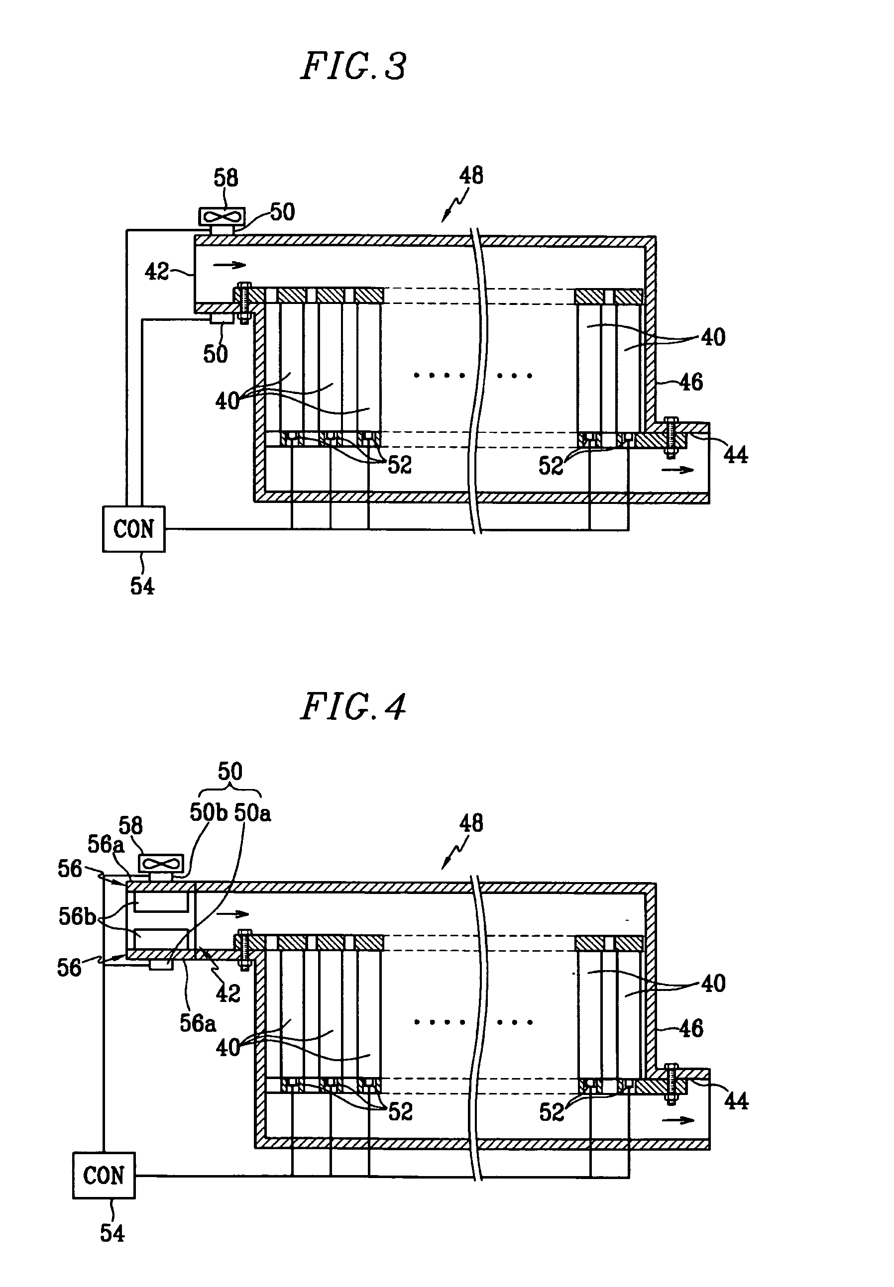
[0050]FIG. 3 shows a system according to the present invention. The battery module 48 of the system includes unit batteries 40, each with an electrode assembly having a positive plate, a negative plate, and a separator interposed between the positive plate and the negative plate to generate unit power. A housing 46 has an inlet 42 for receiving a temperature controlling air formed on one side thereof to control the temperature of the unit batteries 40, and an outlet 44 for discharging the air passing through the unit batteries 40 formed on the other side facing the one side. The unit batteries 40 are arranged and spaced apart at a predetermined distance. The system further includes a thermoelectric elements 50 formed in the inlet 42 of the housing 46 to increase or decrease the temperature of the air flowing inside the housing 46 through the inlet 42.

[0051] Also, the system includes temperature sensors 52 mounted on one side of the respective unit batteries 40 to detect the temperat...


PUM

PropertyMeasurementUnit
temperatureaaaaaaaaaa
thermoelectricaaaaaaaaaa
temperaturesaaaaaaaaaa

Abstract

A system which can efficiently control the temperature of the battery module, and also can easily control the temperature in the intense environment by actively adapting the exterior environment. The system for controlling temperature of a secondary battery module includes a housing receiving a plurality of unit batteries. The housing has an inlet and an outlet. A heat transfer member is in contact with the unit batteries. The heat transfer member has a portion exposed to a heat transfer medium duct formed inside the housing, and a temperature controller is mounted in the heat transfer member to control temperature of the unit batteries.

Description

CROSS-REFERENCE TO RELATED APPLICATION [0001] This application claims priority to and the benefit of Korean Patent Application No. 10-2004-0076439 filed on Sep. 23, 2004 in the Korean Intellectual Property Office, the entire disclosure of which is incorporated herein by reference. FIELD OF THE INVENTION [0002] The present invention relates to a secondary battery, and more particularly, to a system for controlling temperature of a secondary battery module in which the battery module is formed by connecting unit batteries. BACKGROUND OF THE INVENTION [0003] Non-aqueous electrolyte secondary batteries of high energy density have recently been developed as high power secondary batteries, and bulk size batteries are formed by serially connecting several to tens of the high power secondary batteries to be suitable for machine motor drives requiring high power sources, such as hybrid electric vehicles. [0004] Such a bulk size secondary battery assembly (“battery module”) typically includes...

Claims


Application Information

Patent Timeline
Patent Type & Authority Applications(United States)
IPC IPC(8): H01L35/28H01M10/60H01M10/613H10N10/10H01M10/615H10N10/13H01M10/625H01M10/633H01M10/637H01M10/647H01M10/6551H01M10/6552H01M10/6554H01M10/6556H01M10/6563H01M10/6572H01M10/663
CPCF28D2021/0029H01M10/052H01M10/486H01M10/5004H01M10/5006Y02T10/7011H01M10/502H01M10/5053H01M10/5067H01M10/5073H01M10/5085H01M10/5016H01M10/625H01M10/63H01M10/615H01M10/6563H01M10/6554H01M10/6572H01M10/6566H01M10/613Y02E60/10H01M10/6568
Inventor KIM, TAE-YONG
Owner SAMSUNG SDI CO LTD
Learn More