
Unmanned utility vehicle

Inactive Publication Date: 2006-03-23
TORO CO THE
View PDF65 Cites 72 Cited by
  • Summary
  • Abstract
  • Description
  • Claims
  • Application Information

AI Technical Summary

Benefits of technology

[0012] The subject invention provides an unmanned utility vehicle for traversing a plot of land having improved safety. The vehicle comprises a carriage having first and second drive wheels for moving over the plot of land and first and second electric drive motors operatively connected to first and second drive wheels. A first drive motor controller is operatively connected to the first electric drive motor and a second drive motor controller is operatively connected to the second electric drive motor. The vehicle also comprises at least one tool supported by the carriage for operation, at least one electric tool motor engaging the tool and supported by the carriage, and a tool motor controller operatively connected to the electric tool motor. A main controller communicates with the drive motor controllers and the tool motor controller to control the electric drive and tool motors. A controller area network interconnects the main controller, the drive motor controllers, and the tool motor controller for facilitating communication therebetween to improve operation and modularity of the vehicle. A plurality of sonar sensors mounted about said carriage for detecting objects and transmitting a signal to said main controller to deactivate or reduce at least one of said electric drive motors and said electric tool motor in response to detecting the object.
[0013] The subject invention provides a utility vehicle having improved safety that overcomes the related art vehicles. Specifically, the subject invention provides a small, lightweight, and energy efficient vehicle.

Problems solved by technology

One disadvantage of these vehicles is that operation of the internal combustion engines to power the tool is a drain on the internal combustion engine and requires operating the internal combustion engine at various speeds to perform the task.
Operating at various RPM uses significantly more gas and also produces different harmonics at each of the different speeds which results in additional noise from the vehicle.
Another disadvantage is that if the electrical motors malfunction, the vehicle may continue to operate without the malfunction being detected.
When such a malfunction is detected, the complexity of these unmanned systems requires the vehicle to be out of commission for various lengths of time.
Further, these systems tend to be quite expensive so additional vehicles are generally not available to continue in place of the malfunctioning vehicle.
This requires the electric motors to be significantly more powerful and larger to propel the vehicle, which results in heavier vehicles.
These heavier vehicles are likely to damage terrain by leaving large ruts or gouges during operation.
Another disadvantage is that these electrical motors tend not to be modular, such that if one of the motors malfunctions or breaks, a new motor specific for such operation must be utilized on the vehicle.
Electric motors are quieter and have less maintenance but their power output is limited.
A cord limits where the mower can travel and batteries are heavy and have limited power from a practical standpoint.
The industry does not consider a battery-powered mower that will run over 2 hours cost effective due to the size, weight, and cost of the batteries.
The one exception is the greens mower but it has a limited application because greens have relatively small area to cut.

Method used


Image

  • Unmanned utility vehicle
  • Unmanned utility vehicle
  • Unmanned utility vehicle

Examples


Embodiment Construction

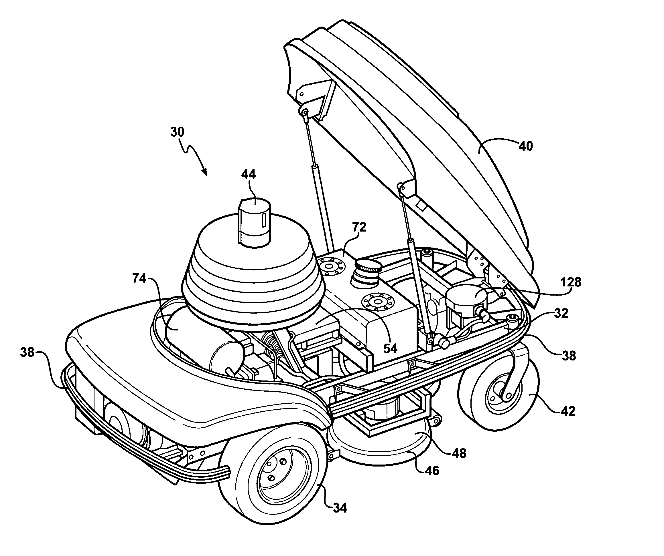
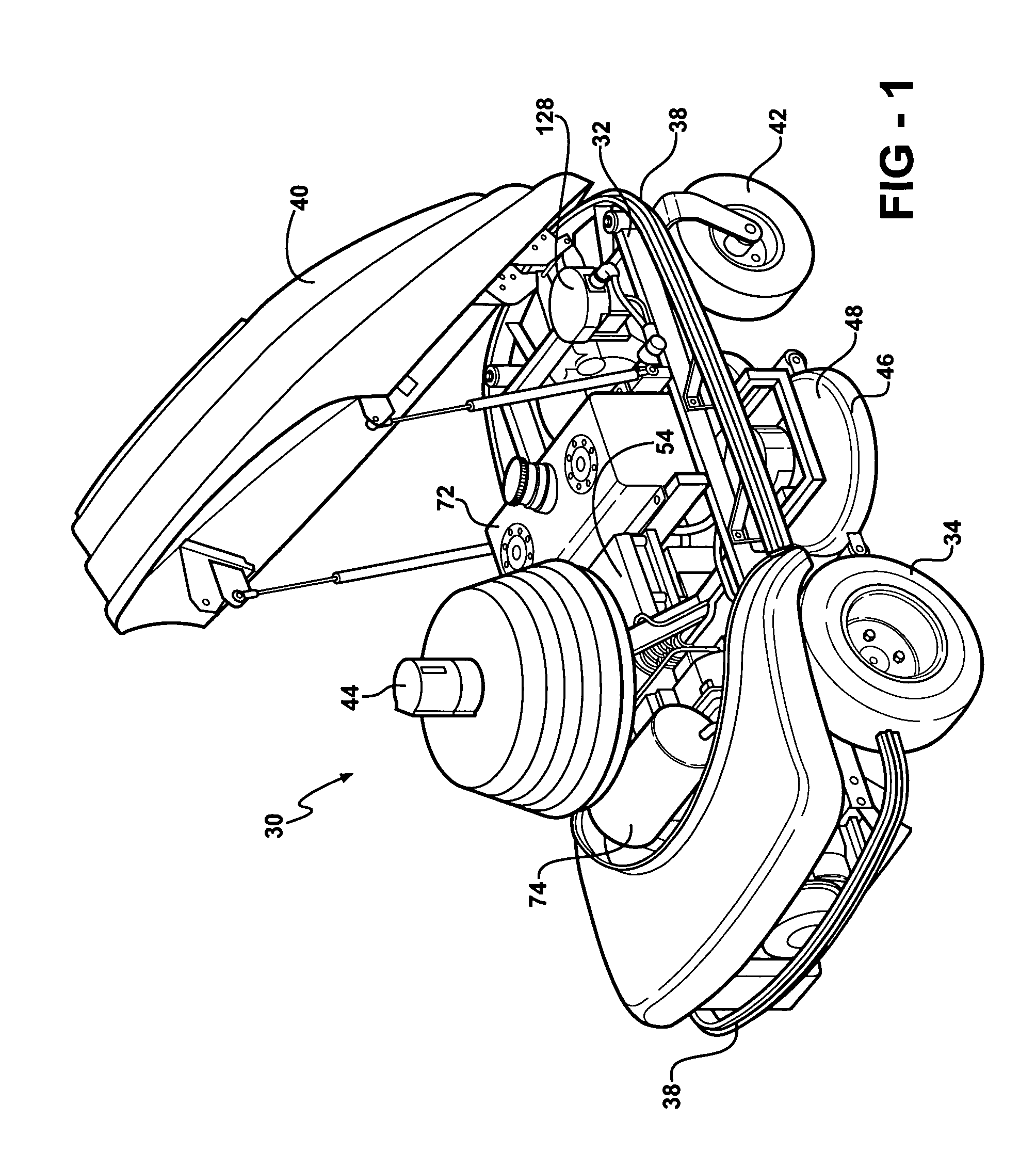
[0040] Referring to the Figures, wherein like numerals indicate corresponding parts throughout the several views, an unmanned utility vehicle 30 for traversing a plot of land is shown generally at in FIG. 1. The unmanned utility vehicle 30 may include, but is not limited to, an autonomous lawn mower, vacuum cleaner, sweeper, or scrubber, polisher, sander, or buffer, beach cleaner, ice groomer, or line painter.

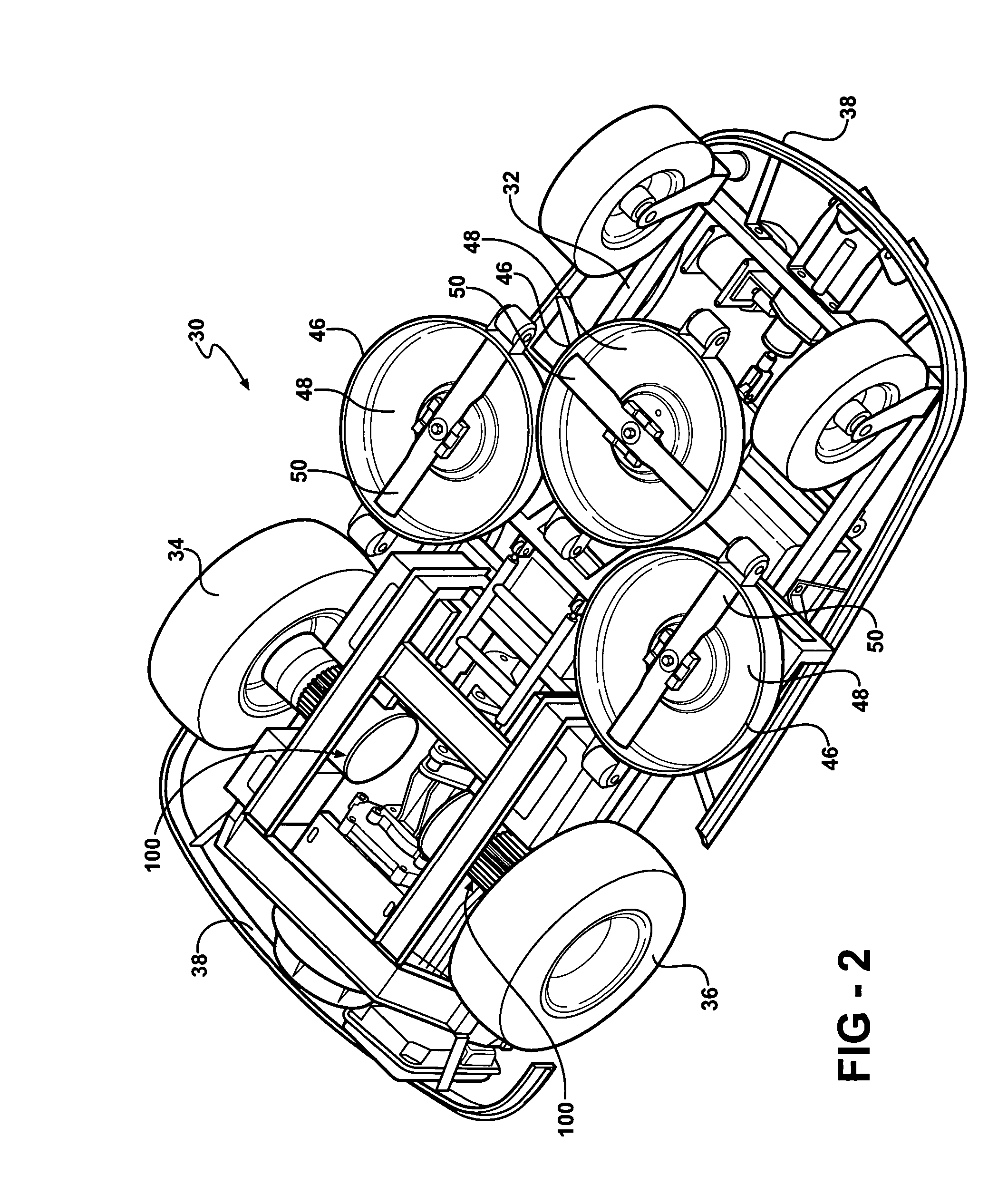
[0041] The vehicle 30 includes a carriage 32 having first and second drive wheels 34, 36 for moving over the plot of land, a bumper 38, and a cover 40. With reference to FIG. 1, the cover 40 is movable between an open position and a closed position with the cover 40 being shown in the open position. The vehicle 30 may also includes at least one non-drive, or dummy, wheel that is driven by the drive wheels 34, 36. For example, the non-drive wheel 42 may be a caster-type wheel that is capable of swiveling in multiple directions. Alternatively, the vehicle 30 have each of the whe...


PUM


Abstract

An unmanned utility vehicle (30) for traversing a plot of land is disclosed that includes a carriage (32) having first and second drive wheels (34, 36) for moving over the plot of land, a guidance assembly (44) for guiding the vehicle (30) about the plot, and at least one tool (46) for performing an operation. The vehicle (30) includes first and second electric drive motors (56, 58) operatively connected to the respective drive wheels (34, 36) and at least one electric tool motor (60) engaging the tool (46). A plurality of sonar sensors (94) are supported by said carriage (32) for detecting objects near said utility vehicle (30) such that the utility vehicle (30) is deactivated or slowed in response to detecting the object.

Description

CROSS REFERENCE TO RELATED APPLICATION [0001] This application claims the benefit of U.S. Provisional Patent Application Ser. Nos. 60 / 609,520 filed Sep. 13, 2004.BACKGROUND OF THE INVENTION [0002] 1. Field of the Invention [0003] The subject invention relates to an unmanned utility vehicle for traversing a plot of land having improved safety systems. [0004] 2. Description of the Related Art [0005] Various unmanned utility vehicles, such as autonomous lawn mowers, are known to those of ordinary skill in the art and typically include a carriage having a plurality of drive wheels for moving over the plot of land. The drive wheels are driven by an electric motor powered by batteries. The vehicle also includes at least one tool, such as a cutting assembly, supported by the carriage that is powered by an internal combustion engine. In other words, the internal combustion engine is directly engaging and driving the cutting assembly and the electric motors are only driving the drive wheels ...

Claims


Application Information

Patent Timeline
IPC IPC(8): A01D34/00
CPCA01D34/008
Inventor ANGOTT, PAUL G.
Owner TORO CO THE
Learn More