
Retainer, exposure apparatus, and device fabrication method

a technology attachment brackets, applied in the direction of microlithography exposure apparatus, mountings, instruments, etc., can solve the problems of diffraction optical elements, eagerly studied recently, and easy deformation by their own weight, so as to achieve the desired optical performance, reduce aberration, and improve imaging performance

Inactive Publication Date: 2006-03-16
SUDOH YUJI
View PDF4 Cites 8 Cited by
  • Summary
  • Abstract
  • Description
  • Claims
  • Application Information

AI Technical Summary

Benefits of technology

The present invention provides a retainer, exposure apparatus, and device fabrication method that can improve optical performance by reducing aberration caused by deformation and positional offset of an optical element. The retainer includes support members and elastic members that apply elastic force to the optical element in a perpendicular direction. The exposure apparatus includes the retainer and an optical system for exposing a pattern on a mask or reticle onto an object. The device fabrication method involves exposing a pattern on a mask and developing the exposed object. Overall, the invention improves the accuracy and quality of optical performance in various applications.

Problems solved by technology

In particular, the projection lens tends to have a larger caliber and a larger lens capacity due to the recent high NA in the projection optical system, and easily deforms by its own weight.
In addition, diffraction optical elements, which have been eagerly studied recently, also tend to deform due to its thinness.
However, Japanese Patent Application, Publication No. 2001-284226 does not consider the flatness of the lens support points 1200 and lens deformation.
Thus, this reference has a difficulty in realizing a projection optical system with little aberration due to such a lens's deformation.
This causes the lens to incur a large load from the spring members of the flex mount parts 2200.
This causes the large birefringence and possibly breaks the lens, and has a difficulty in realization.

Method used


Image

  • Retainer, exposure apparatus, and device fabrication method
  • Retainer, exposure apparatus, and device fabrication method
  • Retainer, exposure apparatus, and device fabrication method

Examples


Embodiment Construction

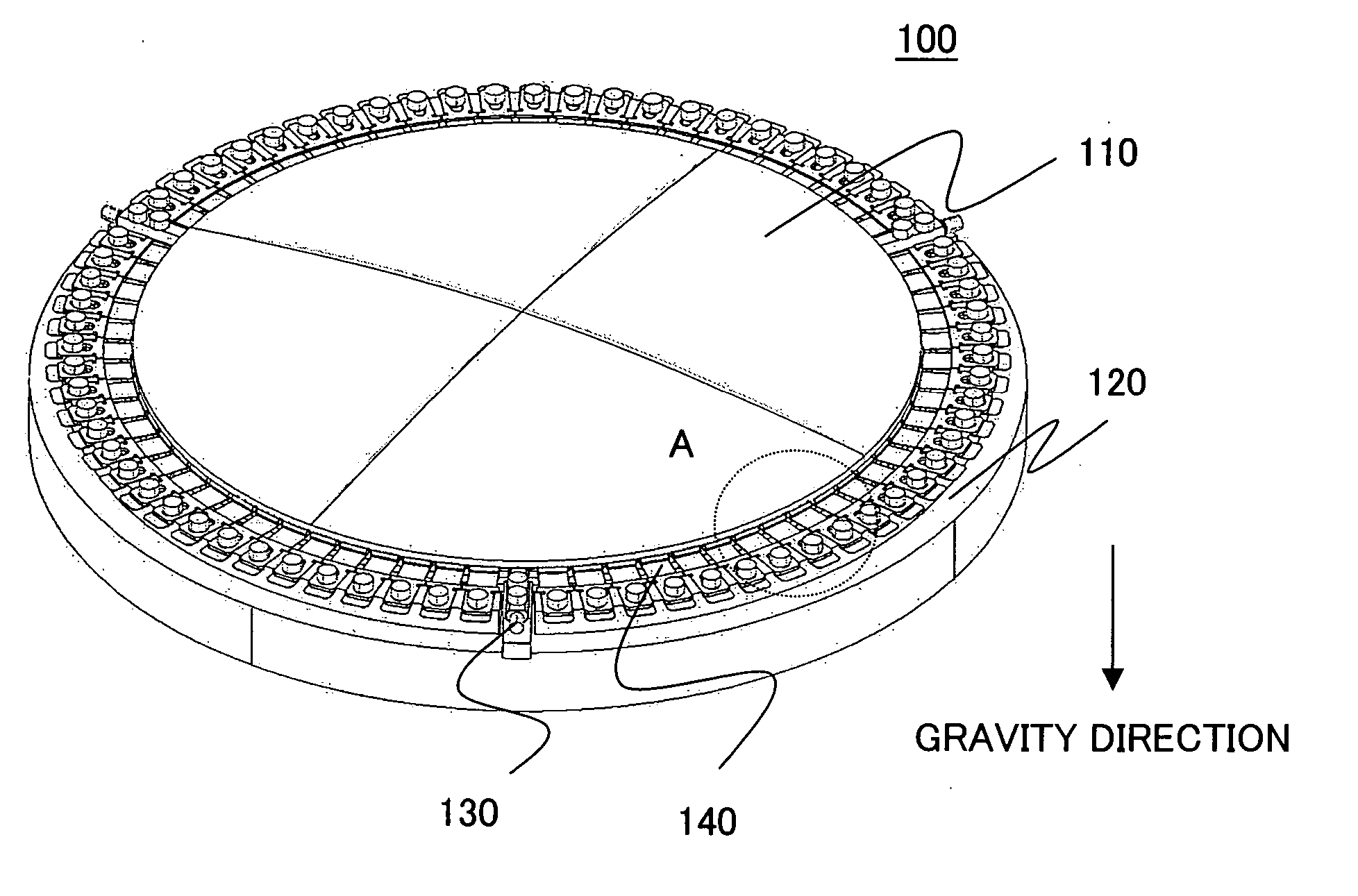
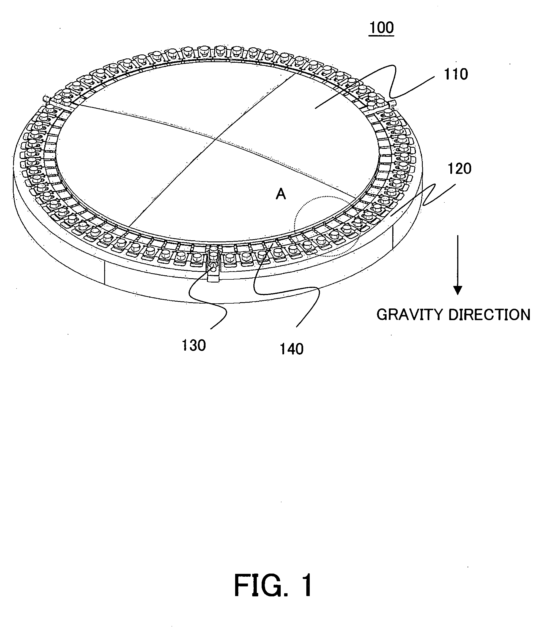
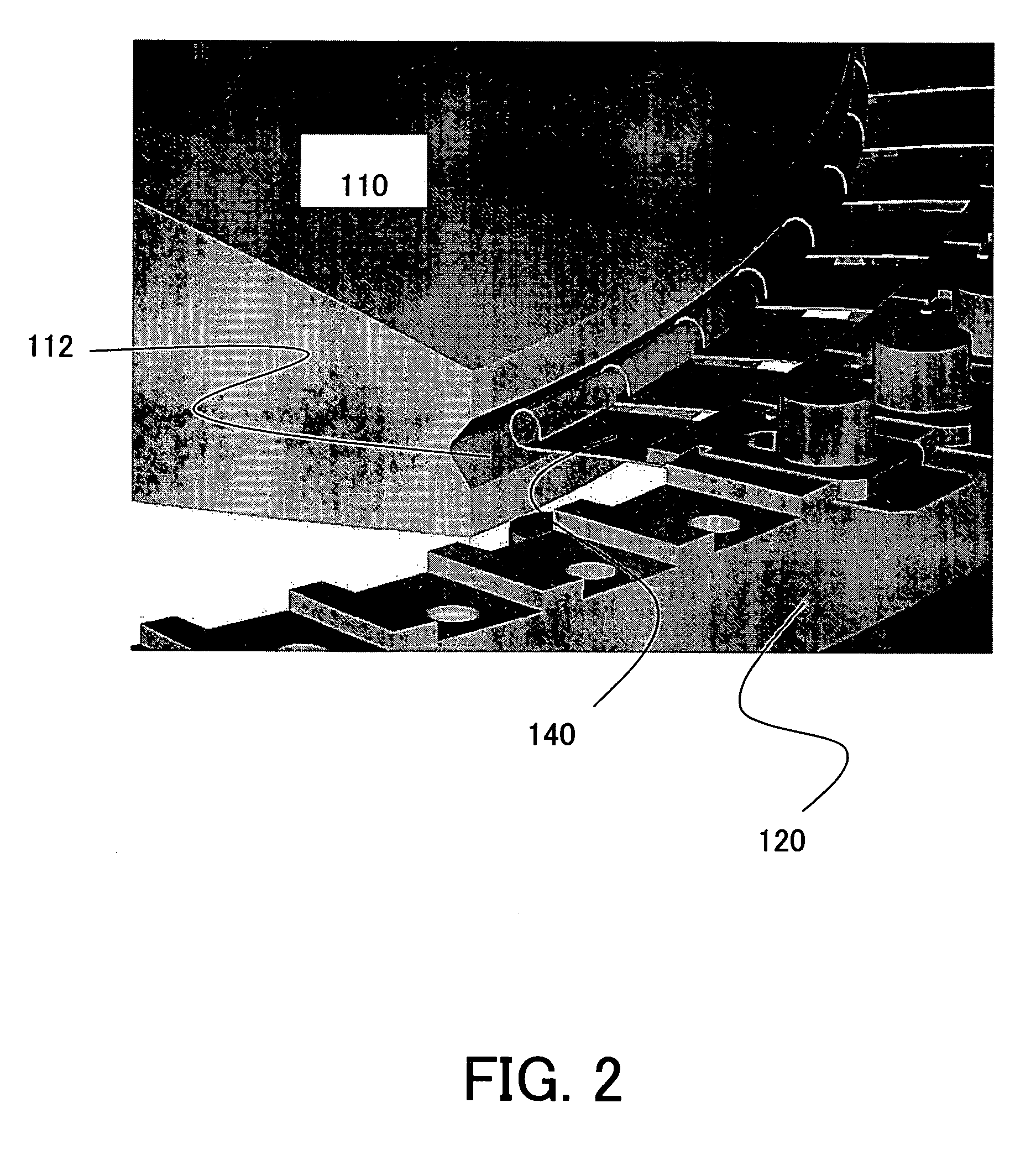
[0029] Referring now to accompanying drawings, a description will be given of an illustrative retainer 100 and exposure apparatus 200 of the present invention. However, the present invention is not limited to these embodiments, and each element may be replaced within a scope of this invention. For example, although the retainer 100 is applied to a projection optical system 230 in the exposure apparatus 200 in the instant embodiment, it is applicable to an illumination optical system 214 in the exposure apparatus 200 and other known optical systems. Here, FIG. 1 is a schematic sectional and perspective view of the inventive retainer applicable to the projection optical system in the exposure apparatus 200. The gravity direction and the antigravity direction (i.e., a direction opposing to the gravity direction) are parallel to the optical axis of the optical element 110, as shown in an arrow direction in FIG. 1. When the optical axis of the optical element is parallel to the gravity a...


PUM

PropertyMeasurementUnit
angleaaaaaaaaaa
wavelengthaaaaaaaaaa

Abstract

A retainer includes a plurality of support members for supporting an optical element, and a plurality of elastic members arranged between the plurality of support members, each elastic member applying an elastic force to the optical element in a direction perpendicular to a gravity direction.

Description

[0001] This application is a continuation of prior application Ser. No. 10 / 851,955, filed May 21, 2004, the contents of which are hereby incorporated by reference in their entirety.[0002] This application claims a benefit of foreign priority based on Japanese Patent Application No. 2003-144096, filed on May 21, 2003, which is hereby incorporated by reference herein in its entirety as if fully set forth herein. BACKGROUND OF THE INVENTION [0003] The present invention relates generally to precision machines for mounting an optical element, and more particularly to a projection optical system in an exposure apparatus, etc. The present invention is suitable, for example, for a retainer that holds an optical element for a more precise imaging relationship in an exposure apparatus in projecting and exposing an image on an original sheet, such as a mask or reticle (these terms are used interchangeably in this application) onto an object, such as a single crystal substrate for a semiconduct...

Claims


Application Information

Patent Timeline
Patent Type & Authority Applications(United States)
IPC IPC(8): G02B7/02G02B7/00G02B7/182G02B7/183G03F7/20H01L21/027
CPCG02B7/006G02B7/183G02B7/027
Inventor SUDOH, YUJI
Owner SUDOH YUJI
Learn More