
Manufacturing method and joining device for solid-state imaging devices

a technology of solid-state imaging and manufacturing methods, which is applied in the direction of semiconductor devices, electrical equipment, basic electric elements, etc., can solve the problems of unsatisfactory product quality, unfavorable product quality, and prone to faulty joining, so as to achieve satisfactory product quality and high level of aligning accuracy

Inactive Publication Date: 2006-03-09
FUJIFILM CORP +1
View PDF68 Cites 29 Cited by
  • Summary
  • Abstract
  • Description
  • Claims
  • Application Information

AI Technical Summary

Benefits of technology

[0011] An object of the present invention, attempted in view of this circumstance, is to provide a manufacturing method and joining device for solid-state imaging devices which make possible prevention of faulty adhesion, which would give rise to rejectable products, in cutting or otherwise machining a laminated structure composed of a substrate (wafer) and a planar member (glass plate), which are joined together, such as a chip size package (CSP) type solid imaging device.
[0023] As described so far, the solid imaging device manufacturing method according to the invention enables the wafer and the transparent flat plate to be joined together with the spacer in-between without allowing any trouble, which would give rise to faulty adhesion, to occur and thereby the quality of products to be kept satisfactory.

Problems solved by technology

However, the art disclosed in Japanese Patent Application Laid Open No. 2002-231921 involves a problem that, when the transparent glass plate and the wafer are stuck together, uneven thicknesses of the transparent glass plate and the wafer might invite faulty joining. FIG. 20, illustrating this phenomenon, is an expanded sectional view of the essential part of a state in which the transparent glass plate 1 and the wafer 2 are stuck together.
However, if there is any portion of faulty adhesion between the layer of the spacers 5 and the wafer 2 as referred to above, the dicing fluid 9 will infiltrate into the gap 6 to make it impossible to maintain acceptable standards of the products.

Method used


Image

  • Manufacturing method and joining device for solid-state imaging devices
  • Manufacturing method and joining device for solid-state imaging devices
  • Manufacturing method and joining device for solid-state imaging devices

Examples


Embodiment Construction

[0045] A preferred embodiment of the solid imaging device manufacturing method according to the present invention will be described in detail below with reference to accompanying drawings. In these drawings, the same members are designated by respectively the same reference numbers or characters.

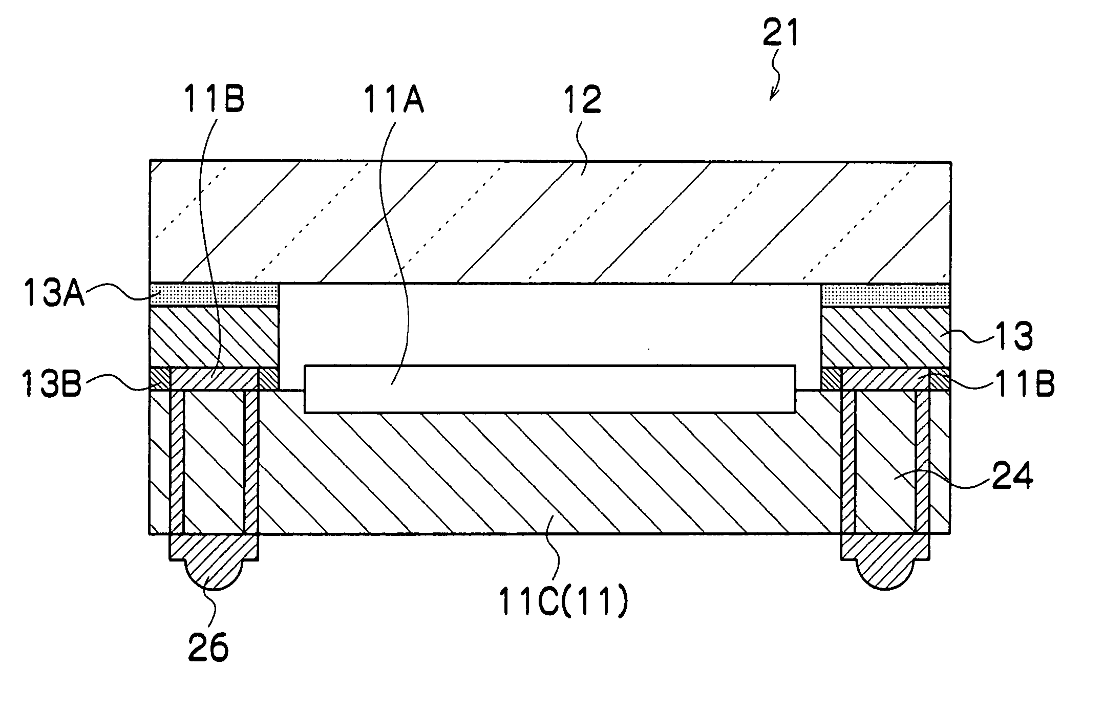
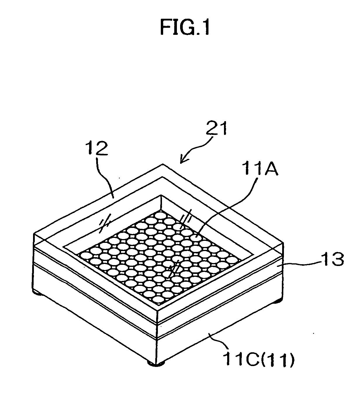
[0046]FIG. 1 and FIG. 2 show a perspective view of the external shape and a sectional view of the essential part, respectively, of a chip size package (CSP) type solid imaging device fabricated by a solid imaging device manufacturing method according to the invention.

[0047] A solid imaging device 21 comprises a solid imaging element 11A; a rectangular solid imaging element 11C provided with pads 11B, 11B . . . , which are a plurality of connection terminals to be electrically connected to the solid imaging element 11A; frame-shaped spacers 13 so fitted over the solid imaging element chip 11C as to surround the solid imaging element 11A; and a transparent glass plate 12 fitted over these sp...


PUM


Abstract

The present invention provides a method of manufacturing solid-state imaging devices comprising the steps of: forming a large number of solid-state image sensing devices over a wafer; forming, in positions matching said solid-state image sensing devices on the under face of a transparent flat plate to be joined to said wafer, frame-shaped spacers of a prescribed thickness each in a shape of surrounding an individual solid imaging element; aligning said wafer and said transparent flat plate opposite each other; supporting with a fixed table substantially the whole of one of the under face of said wafer and the upper face of said transparent flat plate, supporting substantially the other face with a pressing member via an elastic member, and thereby joining said wafer and said transparent flat plate via said spacers by the pressing member; and splitting said wafer and said transparent flat plate individual solid-state image sensing devices.

Description

BACKGROUND OF THE INVENTION [0001] 1. Field of the Invention [0002] The present invention relates to a manufacturing method and a joining device for solid-state imaging devices, and more particularly to a manufacturing method and a joining device for solid-state imaging devices suitable for the manufacture of chip size package (CSP) type solid-state imaging devices. [0003] 2. Related Art [0004] Today, even further size reductions are required of solid-state imaging devices, consisting of CCDs or CMOSs, for use in digital cameras and mobile telephones. For this reason, the main stream is now shifting from conventional large packages, in each of which a whole solid imaging element chip is sealed airtight into a package of ceramic or some other material to chip size packages (CSPs), each about as large as a solid imaging element chip itself. [0005] In this context, there is proposed a method by which spacers are formed on a transparent glass plate correspondingly to positions of surrou...

Claims


Application Information

Patent Timeline
Patent Type & Authority Applications(United States)
IPC IPC(8): H01L21/00
CPCH01L27/14683H01L27/14618H01L2924/0002H01L2924/16235H01L2924/00
Inventor YAMAMOTO, KIYOFUMITAKASAKI, KOUSUKEOKUTSU, KAZUO
Owner FUJIFILM CORP
Learn More