
Hydrogen storage and integrated fuel cell assembly

a fuel cell and hydrogen storage technology, applied in the field of hydrogen storage, can solve the problems of many tank materials not being able to stand up to hydrogen diffusion, flammability or explosion safety risks, and problems such as problems such as difficulty in ensuring the safety of the environment, and achieve the effect of improving heat transfer and easy replacement of materials

Inactive Publication Date: 2006-03-09
GROSS KARL J
View PDF26 Cites 87 Cited by
  • Summary
  • Abstract
  • Description
  • Claims
  • Application Information

AI Technical Summary

Benefits of technology

[0014] The present invention overcomes the disadvantages of prior art by providing for hydrogen storage that allows for improved heat transfer into and out of a hydrogen-storage material. In one embodiment of the present invention, the hydrogen-storage material is segmented into internal volumes that allows for tailoring of the hydrogen storage capabilities and easy replacement of materials.
[0016] It is another aspect of the present invention to provide a fuel cell-hydrogen storage system that has improved thermal matching of the fuel cell and hydrogen-storage material.

Problems solved by technology

Hydrogen is a gas under ambient conditions and has a small volumetric energy density, and as such hydrogen storage is problematic.
One problem with tanks is that hydrogen is and can easily diffuse through metals, especially under high pressure, presenting flammability or explosion safety risks.
Many tank materials cannot stand up to hydrogen diffusion at high pressures for a long period of time.
In addition, high-pressure tanks are generally heavy and bulky, resulting in a large penalty, especially for transportation applications.
Finally, hydrogen stored at high pressures presents safety risks associated with a catastrophic release of the compression energy of the gas.
These devices are rather cumbersome and have very high energy penalties associated with liquefying the hydrogen.
Because it is necessary to maintain the liquid hydrogen at a temperature of 20 K, there are efficiency and safety problems associated with the evaporation of hydrogen that occurs under normal conditions.
Although high pressures and extreme temperatures are not necessarily required for these materials to store hydrogen, many of the proposed hydrogen-storage materials systems are generally heavier than the hydrogen gas and liquid storage systems, and thus weight is an issue.
Thermal management is also an issue with fuel cells and with metal hydrides.
When large amounts of hydrogen are required, however, heat must be supplied to the fuel storage unit to maintain high desorption rates.
Another problem with metal hydrides and many other hydrogen-storage materials is that desorption typically requires about a sixth of the chemical energy available in the hydrogen, reducing the power available from a fuel cell-metal hydride system.
While D-R materials have the potential to store more hydrogen per unit volume with a smaller mass of material than classic metal hydrides, there are several difficulties involved with the use of D-R materials.
The use of beds of D-R materials for storing hydrogen is thus limited, in part, by thermal considerations.
This presents several problems.
First pumping the water adds addition complexity, cost and energy penalties to the system.
Second, water can be corrosive to the fuel cell and fuel storage unit housing, and is also highly reactive with some hydrides.

Method used


Image

  • Hydrogen storage and integrated fuel cell assembly
  • Hydrogen storage and integrated fuel cell assembly
  • Hydrogen storage and integrated fuel cell assembly

Examples


first embodiment

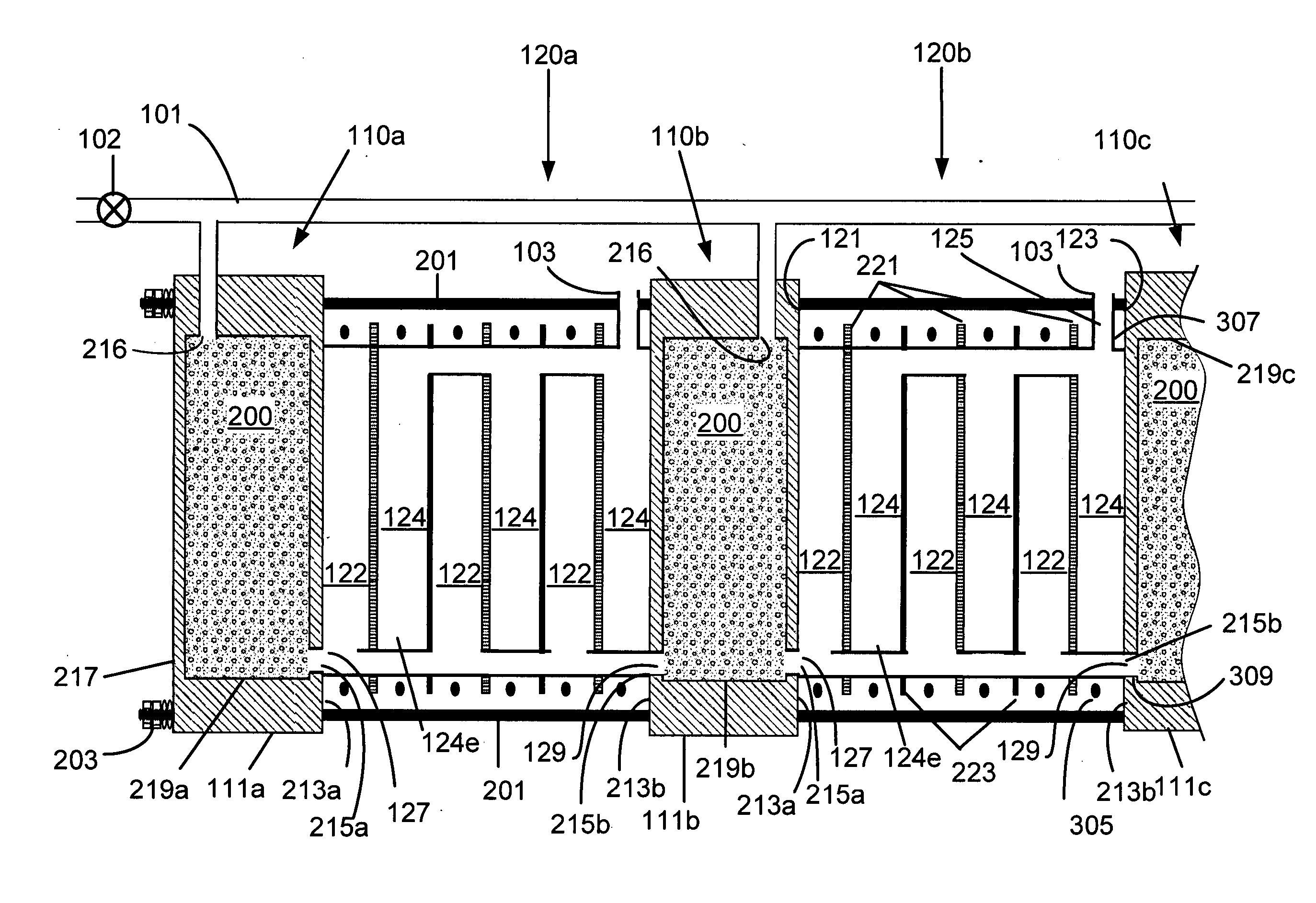
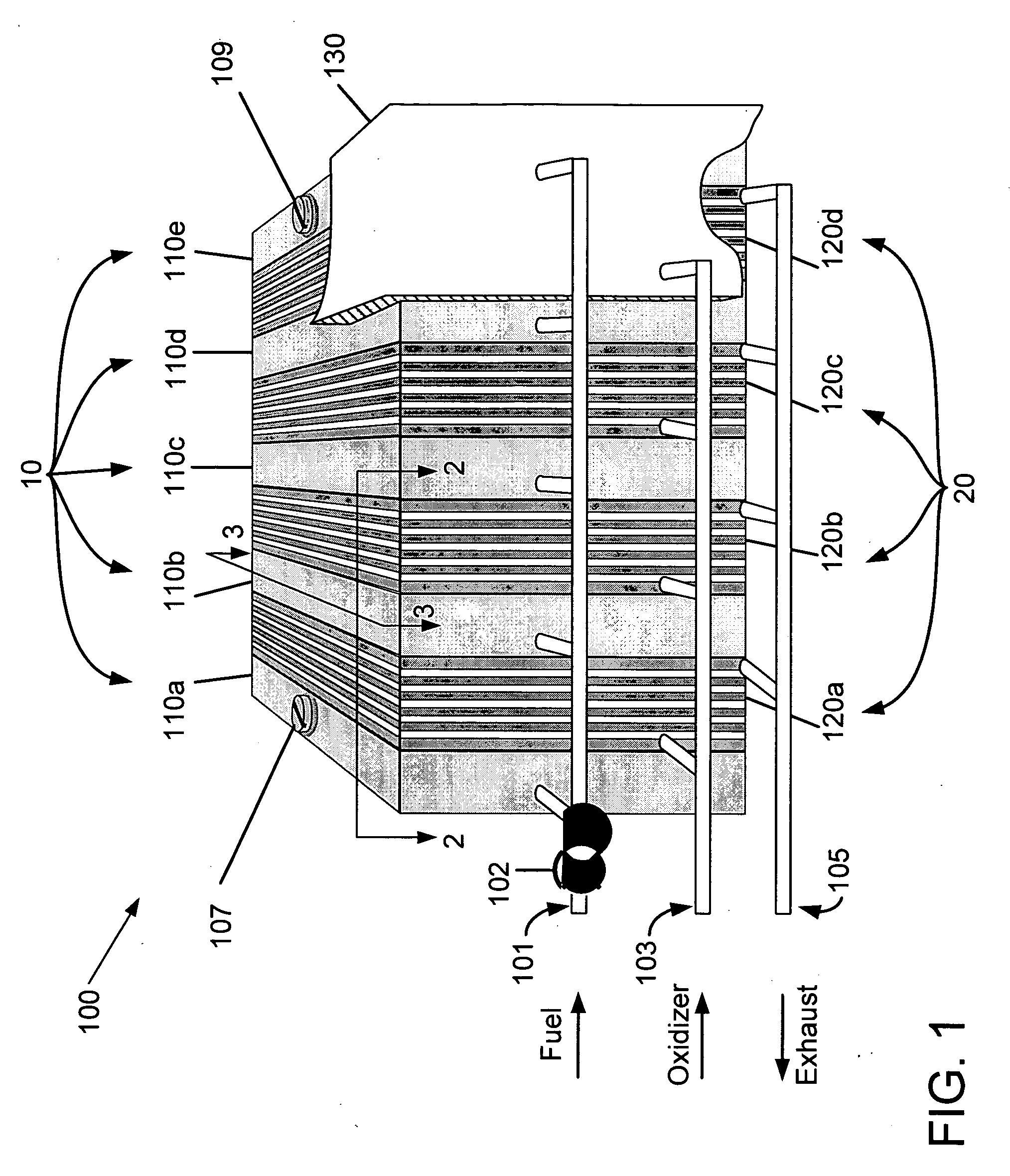
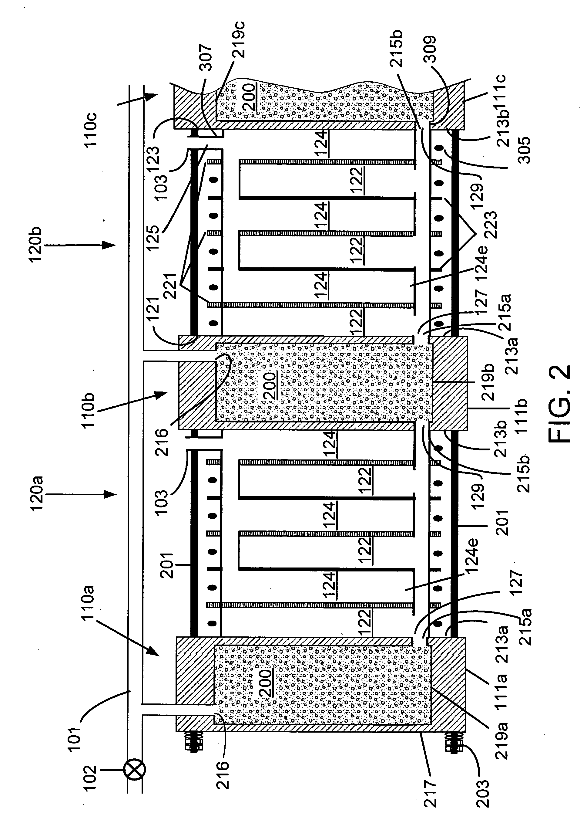
[0040]FIG. 1 is a schematic perspective view of a first embodiment integrated hydrogen-powered electricity-producing system 100 of the present invention. System 100 includes hydrogen-storage assembly 10 and fuel cell assembly 20 and provides for electrical connections as an anode 107 and cathode 109. Hydrogen for system 100 is provided by a fuel supply line 101 to controllably provide hydrogen to fuel storage assembly 10, and the oxidizer for the system is provided by an oxidizer supply line 103. In one embodiment, the oxidizer is the oxygen in air, and that air under pressure is delivered to oxidizer supply line 103. Exhaust products from the reaction of fuel and oxidizer, principally water and waste or unused gases, are removed from system 100 through an exhaust line 105.

[0041] The flow of hydrogen gas from fuel supply line 101 into fuel storage assembly 10 is controlled by one or more valves 102. In one embodiment of the present invention, a single valve 102 controls the flow of ...

second embodiment

[0060] A second embodiment fuel storage unit 310 is shown in FIG. 3A as the sectional end view 3-3 of FIG. 1, in sectional end view FIG. 3B of the fuel storage unit without a material 200, in FIG. 4 as a top view 4-4, and in FIG. 5A as a top sectional view 5-5. Fuel storage unit 310 may, in various embodiments, be generally similar to any one or more of the embodiments of fuel storage unit 110 disclosed herein, except as further discussed below, and may be used to provide hydrogen to fuel cell stacks 120, as described herein. Fuel storage unit 310 has volume 219 in housing 111 which includes several cylindrical volumes 303 each having a cover 301 and connected by passageways 305. As is shown in FIGS. 3A, 3B and 5A, passageways 305 connect volume 219 to inlet 216 and outlet 215, and includes passages 304 that connect cylindrical volumes 303, a passage 302 that extends to inlet 216 and a passage 306 that extends to outlet 215. The partitioning of volume 219 into smaller volumes 303 al...

third embodiment

[0062] A third embodiment fuel storage unit 310′ is shown in the FIG. 5B as a top sectional view 5-5 of FIG. 3A. Fuel storage unit 310′ may, in various embodiments, be generally similar to any one or more of the embodiments of fuel storage units 110 or 310 disclosed herein, except as further discussed below, and may be used to provide hydrogen to fuel cell stacks 120 as described herein. Fuel storage unit 310′ has volumes 303 with two different hydrogen-storage materials, indicated as material 200-1 and material 200-2, with a different set of interconnections for each. Thus each volume 303 containing material 200-1 is connected to the hydrogen supply through a passageway 302-1 and to an outlet 215-1 through a passageway 306-1. Each volume 303 containing material 200-2 is connected to the hydrogen supply through a passageway 302-2 and to an outlet 215-2 through a passageway 306-2. Preferably each passageway 302-1 and 302-2 has a controllable valve to allow the flow of hydrogen into t...


PUM

PropertyMeasurementUnit
pressuresaaaaaaaaaa
temperatureaaaaaaaaaa
temperaturesaaaaaaaaaa

Abstract

Hydrogen is stored in materials that absorb and desorb hydrogen with temperature dependent rates. A housing is provided that allows for the storage of one or more types of hydrogen-storage materials in close thermal proximity to a fuel cell stack. This arrangement, which includes alternating fuel cell stack and hydrogen-storage units, allows for close thermal matching of the hydrogen storage material and the fuel cell stack. Also, the present invention allows for tailoring of the hydrogen delivery by mixing different materials in one unit. Thermal insulation alternatively allows for a highly efficient unit. Individual power modules including one fuel cell stack surrounded by a pair of hydrogen-storage units allows for distribution of power throughout a vehicle or other electric power consuming devices.

Description

STATEMENT REGARDING FEDERALLY SPONSORED RESEARCH OR DEVELOPMENT [0001] The United States Government has rights in this invention pursuant to Contract No. DE-AC04-94AL85000 between the United States Department of Energy and the Sandia Corporation for the operation of the Sandia National Laboratories.BACKGROUND OF THE INVENTION [0002] 1. Field of the Invention [0003] The present invention generally relates to hydrogen storage, and more particularly to a system including hydrogen storage and hydrogen consuming devices, such as fuel cells. [0004] 2. Discussion of the Background [0005] The use of fuel cells for power generation and transportation has the potential to provide an efficient and relatively environmentally benign alternative to conventional, combustion-based systems. Since most fuel cells operate on hydrogen, an import component of a fuel cell system is a hydrogen-storage unit to provide the fuel cell hydrogen on demand. Hydrogen is a gas under ambient conditions and has a sm...

Claims


Application Information

Patent Timeline
Patent Type & Authority Applications(United States)
IPC IPC(8): H01M8/04H01M2/02H01M8/06B65B3/00
CPCC01B3/0005C01B2203/066H01M8/04007H01M8/04014H01M8/04208H01M8/04216Y02T90/32H01M8/249H01M2008/1095H01M2250/20Y02E60/327Y02E60/50H01M8/065F17C11/005Y02E60/32Y02T90/40
Inventor GROSS, KARL J.
Owner GROSS KARL J
Learn More