
Methods and systems for controlling mold temperatures

a technology of temperature control and mold, applied in the field of molds, can solve the problems of affecting the mold operation, reducing the quality of preforms, and condensation on the mold, and achieve the effects of rapid cooling of molded articles, reducing cycle time, and reducing mold condensation

Inactive Publication Date: 2006-03-09
CONCENTRATE MFG OF IRELAND
View PDF99 Cites 88 Cited by
  • Summary
  • Abstract
  • Description
  • Claims
  • Application Information

AI Technical Summary

Benefits of technology

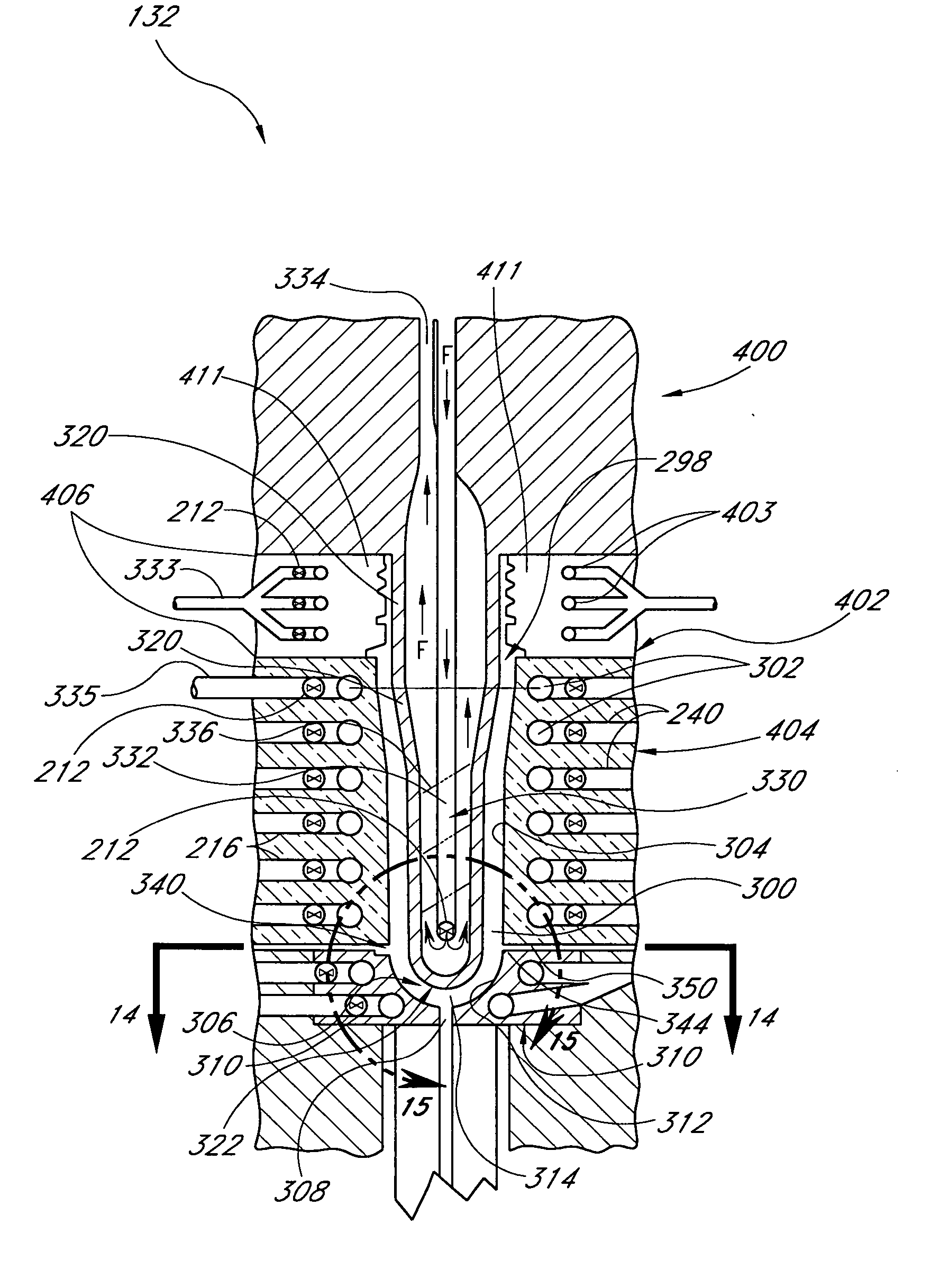
[0016] In some embodiments, one or more temperature sensors are interposed between a molding surface of a mold and at least temperature control element of the mold. In some embodiments, one or more temperature sensors are positioned somewhat proximate to the mold surface. The temperature sensors can accurately measure the temperature of the mold. In some embodiments, a controller is in communication with the temperature sensor. The controller can be configured to selectively control the operation of a valve (e.g., a pressure reducing element) in response to a signal from the temperature sensor. In some embodiments, a mold has a plurality of temperature sensors. The sensors can be positioned at various locations within the material forming the mold.
[0020] In some embodiments, a method of controlling the temperature of a mold for molding a preform comprises providing a core section having a core mold surface. A cavity section having a cavity mold surface and fluid channels is provided. A refrigerant is delivered at a first temperature to a valve system. The valve system outputs the refrigerant at a second temperature, which is less than the first temperature and a temperature of the cavity mold surface. The refrigerant is passed from the valve system through at least one of the cavity section and the core section to reduce the temperature of polymer material disposed between the core mold surface and the cavity mold surface. In some embodiments, the polymer material is in the shape of a preform or closure.
[0027] In some embodiments, molding systems can utilize highly conductive alloys and refrigerants. The combination of high heat transfer materials and refrigerants can provide efficient cooling, or heating, and can minimize cycle time. The high heat transfer materials and refrigerants can be used to rapidly cool molded articles in the mold. The combination of high heat transfer materials and refrigerants can provide efficient and rapid heating of the mold, especially when the mold surfaces are at a low temperature. For example, the mold surfaces can be at a low temperature at the end of a cooling cycle. In some embodiments, the mold surfaces can be warmed so that melt can spread easily through a mold cavity of the mold.
[0028] In some embodiments, a mold is configured to mold an article. At least a portion of the article can have a hardened outer surface. The outer surface can be in the form of a somewhat eggshell like layer. In some embodiments, substantially the entire exterior surface and / or interior surface of an article comprise a hardened outer surface. The interior portions of the articles can be warm and soft when the preform is demolded.
[0029] In some embodiments, a mold can have one or more mold cavities configured to receive moldable material. The mold can have one or more of the following: a core, a cavity section, a gate insert, and a neck finish mold. These components can be heated or cooled by employing a working fluid. The working fluid can be a refrigerant. The working fluid can be used to cool a moldable material positioned within the mold. When the molded article is removed, the working fluid can preheat the mold surfaces so that moldable material, such as a molten polymer, can spread easily through the mold cavity.

Problems solved by technology

The water typically flows continuously throughout the molding operation and may cause condensation to form on the mold.
The condensation may interfere with the molding operation by reducing preform production and decreasing preform quality.
As a result, the potential of mold cooling systems has not been realized.

Method used


Image

  • Methods and systems for controlling mold temperatures
  • Methods and systems for controlling mold temperatures
  • Methods and systems for controlling mold temperatures

Examples


Embodiment Construction

[0069] All patents and publications mentioned herein are hereby incorporated by reference in their entireties. Except as further described herein, certain embodiments, features, systems, devices, materials, methods and techniques described herein may, in some embodiments, be similar to any one or more of the embodiments, features, systems, devices, materials, methods and techniques described in U.S. Pat. Nos. 6,109,006; 6,808,820; 6,528,546; 6,312,641; 6,391,408; 6,352,426; 6,676,883; U.S. patent application Ser. No. 09 / 745,013 (Publication No. 2002-0100566); Ser. No. 10 / 168,496 (Publication No. 2003-0220036); Ser. No. 09 / 844,820 (2003-0031814); Ser. No. 10 / 090,471 (Publication No. 2003-0012904); Ser. No. 10 / 395,899 (Publication No. 2004-0013833); Ser. No. 10 / 614,731 (Publication No. 2004-0071885), provisional application 60 / 563,021, filed Apr. 16, 2004, provisional application 60 / 575,231, filed May 28, 2004, provisional application 60 / 586,399, filed Jul. 7, 2004, provisional applic...


PUM

PropertyMeasurementUnit
viscosityaaaaaaaaaa
pHaaaaaaaaaa
specific gravityaaaaaaaaaa

Abstract

Disclosed is a preferred mold design for producing plastic, molded preforms, which may be blow-molded into a container of a final, desired shape. A preferred mold includes a temperature control system for maintaining the preform mold at a desired temperature. The temperature control system can pass fluid through channels within the preform mold to cool plastic that is injected into the preform mold. In some arrangements, a mold comprises a neck finish mold, the neck finish mold comprising high heat transfer material positioned to transfer heat away from melt within a mold cavity of the mold.

Description

RELATED APPLICATIONS [0001] This application claims the priority benefit under 35 U.S.C. § 119(e) of the provisional application 60 / 578,501, filed Jun. 10, 2004, and 60 / 654,554, filed Feb. 18, 2005, which are hereby incorporated by reference in their entireties.BACKGROUND OF THE INVENTIONS [0002] 1. Field of the Inventions [0003] The inventions relate to molds for producing articles. More specifically, these inventions relate to methods and systems for controlling mold temperatures. [0004] 2. Description of the Related Art [0005] The use of plastic containers as a replacement for glass or metal containers in the packaging of beverages has become increasingly popular. The advantages of plastic packaging include lighter weight, decreased breakage as compared to glass, and potentially lower costs. The most common plastic used in making beverage containers today is PET. Virgin PET has been approved by the FDA for use in contact with foodstuffs. Containers made of PET are transparent, th...

Claims


Application Information

Patent Timeline
Patent Type & Authority Applications(United States)
IPC IPC(8): B29C45/73B29C33/04B29C33/38B29C35/00B29C43/52B29C49/00B29C49/06B29C49/22B29C49/48B29C49/64
CPCB29B2911/1402B29K2105/253B29B2911/14053B29B2911/14066B29B2911/1408B29B2911/14093B29B2911/14113B29B2911/1412B29B2911/1424B29B2911/14246B29B2911/14266B29B2911/14273B29B2911/1428B29B2911/14326B29B2911/14333B29B2911/1444B29B2911/14466B29B2911/14606B29B2911/1464B29B2911/14646B29B2911/14713B29B2911/14773B29C33/046B29C33/3828B29C35/007B29C43/52B29C45/7306B29C45/7337B29C49/0073B29C49/06B29C49/221B29C49/4823B29C2043/527B29C2045/7343B29C2049/4825B29C2049/4833B29C2049/4838B29C2049/4846B29C2049/4853B29C2049/4876B29C2049/4887B29K2105/162B29B2911/14026B29C2949/302B29C2949/3016B29C2949/24B29C2949/22B29C2949/3008B29C2949/3012B29C2949/3026B29C2949/3028B29C2949/3066B29C2949/3064B29C2949/308B29C2949/3078B29C2949/0723B29C2949/0732B29C2949/0724B29C2949/072B29C2949/0733B29C2949/0813B29C2949/073B29C2949/0818B29C2949/0819B29C2949/0777B29C2949/0838B29C2949/0773B29C2949/0829B29C49/071B29C2949/3032B29C2949/0715B29C2049/7864
Inventor HUTCHINSON, GERALD A.LEE, ROBERT A.FEICHTINGER, HEINRICH K.
Owner CONCENTRATE MFG OF IRELAND
Learn More