Water-resistant casing structure for electronic control device
a casing structure and electronic control technology, applied in the direction of electrical apparatus casings/cabinets/drawers, coupling contact members, securing/insulating couplings, etc., can solve the problems of reducing the service life of the electronic control device. b>101/b>, to achieve the effect of minimizing stresses and reliable operation
- Summary
- Abstract
- Description
- Claims
- Application Information
AI Technical Summary
Benefits of technology
Problems solved by technology
Method used
Image
Examples
1st embodiment
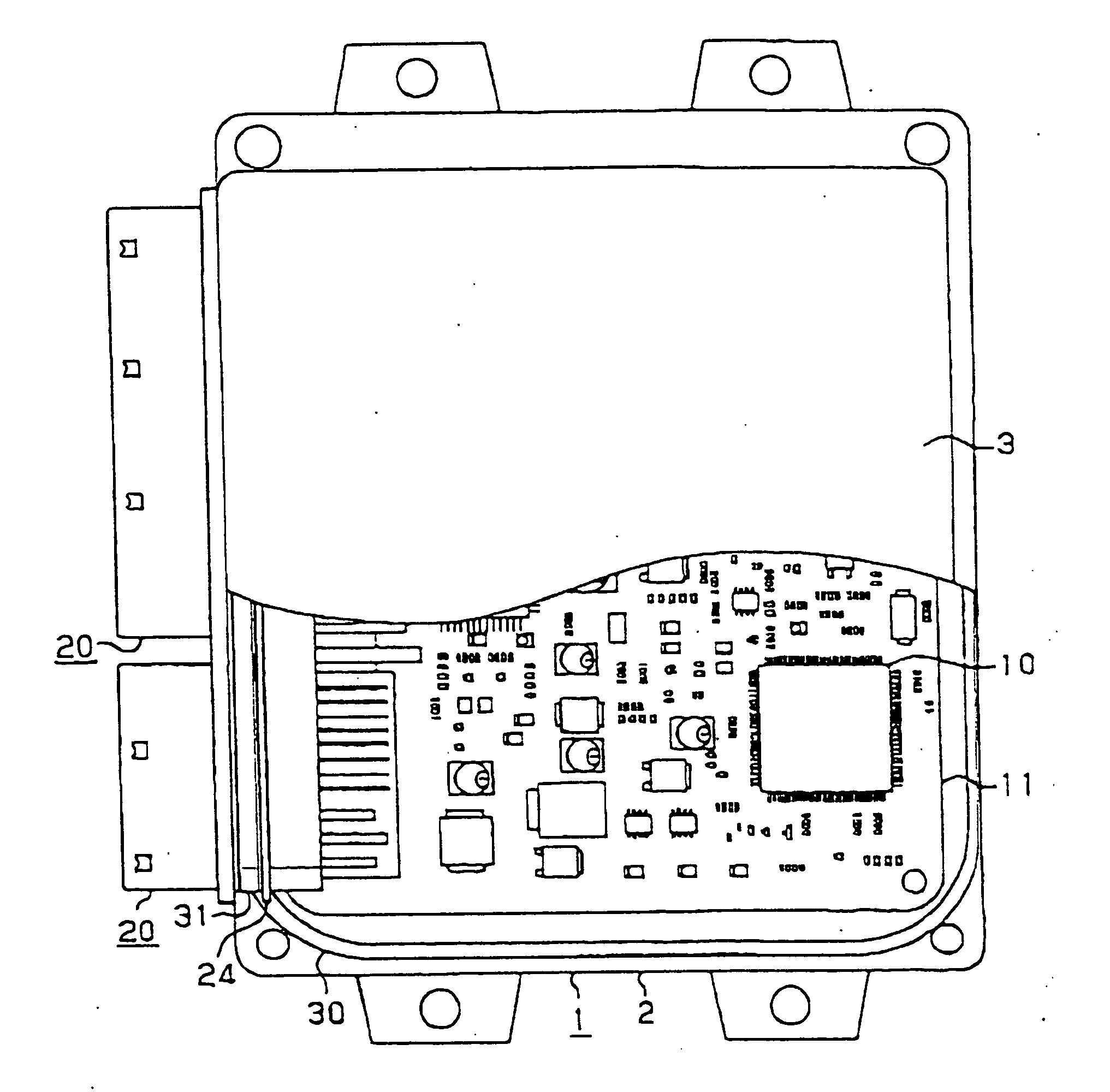
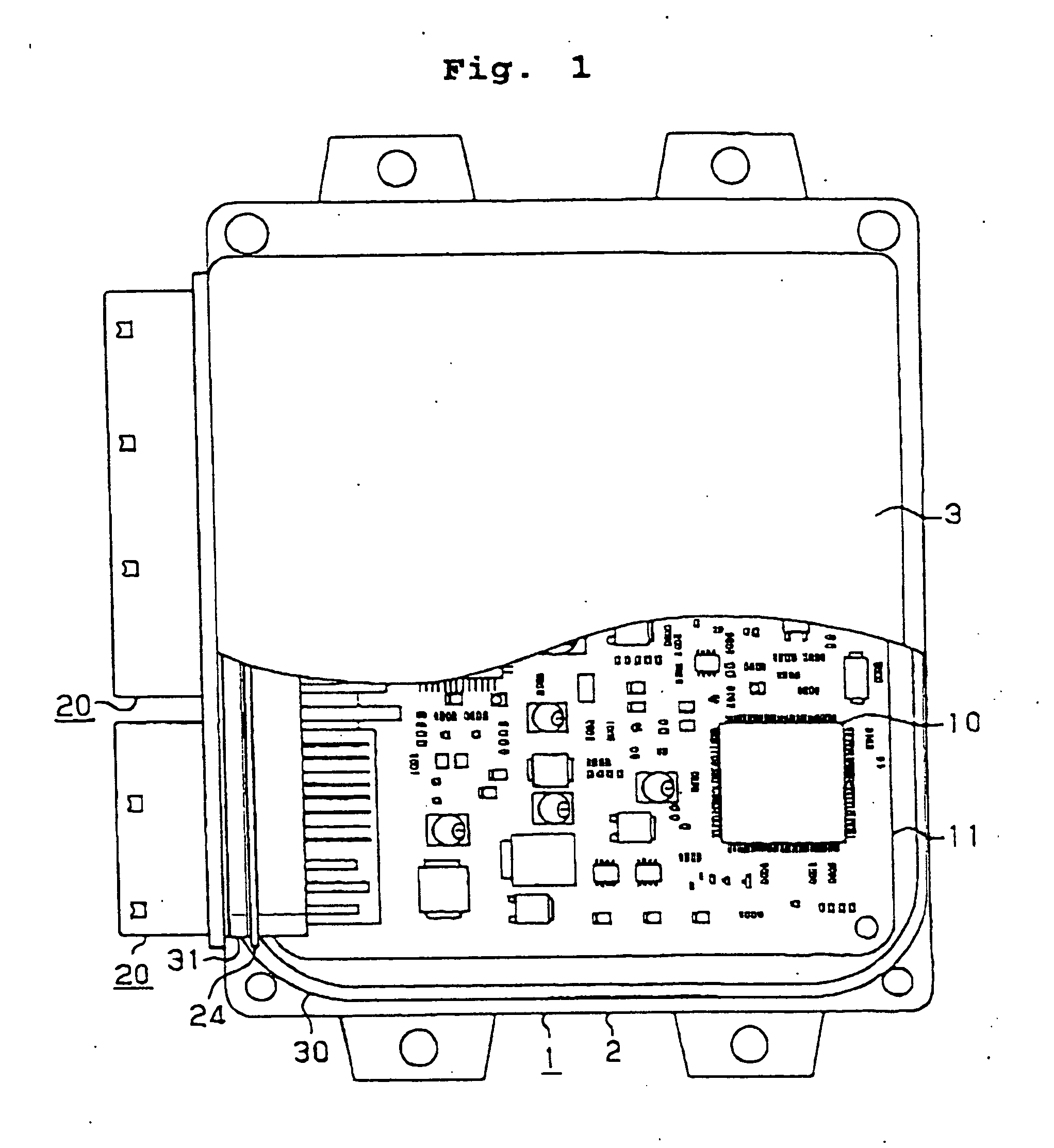
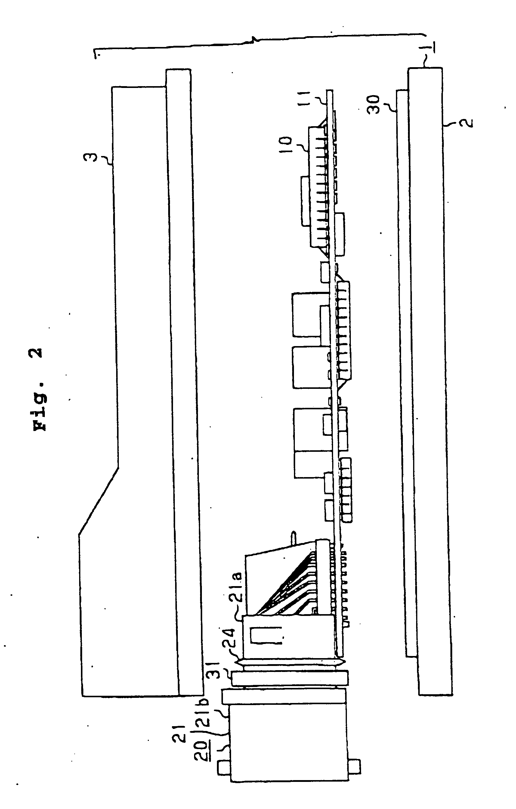
[0043] As shown in FIGS. 1 and 2, a water-resistant casing structure according to a first embodiment of the present invention has a casing 1 housing the electronic control device therein. The casing 1 comprises a lower case 2 serving as a base plate and an upper case 3 serving as a cover. The lower case 2 is in the form of an aluminum die-casting, and the upper case 3 is molded of synthetic resin. The lower case 2 comprises a flat square plate. The upper case 3 comprises a downwardly open square box having a lower opening, and is mounted on the lower case 2 which closes the lower opening of the upper case 3. The lower case 2 and the upper case 3 are fastened to each other by screws, for example, with an annular water-resistant seal 30 interposed therebetween. The annular water-resistant seal 30 hermetically seals the space defined between the lower case 2 and the upper case 3. The box-shaped casing 1 is substantially square in shape as viewed in plan, and has a height much smaller t...
2nd embodiment
[0060] A water-resistant casing structure according to a second embodiment of the present invention will be described below with reference to FIGS. 6, 7, and 8. Only parts of the water-resistant casing structure according to the second embodiment which are different from the water-resistant casing structure according to the first embodiment will be described in detail below.
[0061] According to the second embodiment, as shown in FIGS. 6, 7, and 8, a tooth 60 as a stop is disposed on the casing 1, i.e., the upper case 3 thereof, at a position closely confronting the connector 20 near the region sealed by the water-resistant seat 31.
[0062] Specifically, the inner block member 21a of the connector 21 extends through the joint hole 4 into the casing 1, and has an upper surface closely confronting the upper case 3 of the casing 1. The tooth 60 is disposed at a central position in the horizontal direction in FIG. 7. The tooth 60 is integrally formed with the upper case 3 in a region whic...
3rd embodiment
[0064] A water-resistant casing structure according to a third embodiment of the present invention will be described below with reference to FIGS. 9, 10, and 11. Only parts of the water-resistant casing structure according to the third embodiment which are different from the water-resistant casing structure according to the second embodiment will be described in detail below.
[0065] According to the third embodiment, as shown in FIGS. 9, 10, and 11, a tooth 70 as a stop is disposed on the connector 20, i.e., the inner block member 21a thereof, at a position closely confronting the casing 1 near the region sealed by the water-resistant seat 31.
[0066] Specifically, the tooth 70 is integrally formed with an upper surface of the inner block member 21a in a region which is positioned slightly inwardly of the water-resistant seal 31, i.e., in a region which is not contacted by the water-resistant seal 31. The tooth 70 is disposed at a central position in the horizontal direction in FIG. ...
PUM
 Abstract
Description
Claims
Application Information
 - R&D
- Intellectual Property
- Life Sciences
- Materials
- Tech Scout
- Unparalleled Data Quality
- Higher Quality Content
- 60% Fewer Hallucinations
Browse by: Latest US Patents, China's latest patents, Technical Efficacy Thesaurus, Application Domain, Technology Topic, Popular Technical Reports.
© 2025 PatSnap. All rights reserved.Legal|Privacy policy|Modern Slavery Act Transparency Statement|Sitemap|About US| Contact US: help@patsnap.com


