Image forming apparatus having a multi-layered intermediate transfer belt

a transfer belt and image forming technology, applied in the field can solve the problems of unnecessarily large space occupied by the transfer belt, increase of unused or dead space in the casing, and apparatus lack of image forming apparatus advantages provided by the transfer bel

Inactive Publication Date: 2006-03-02
KYOCERA CORP
View PDF4 Cites 4 Cited by
  • Summary
  • Abstract
  • Description
  • Claims
  • Application Information

AI Technical Summary

Benefits of technology

[0075] With thus composed driving roller, stable driving of the intermediate transfer belt can be materialized without giving the intermediate transfer belt a big distortion, without enlarging the apparatus itself and further without generating a drawback of leaving concavity and convexity on the surface of the intermediate transfer belt which communicate the driving force.

Problems solved by technology

The image forming apparatus shown in FIG. 1 has a primary transfer part where intermediate transfer belt 21 is horizontally disposed, which results in the space occupied by the belt becoming unnecessarily large.
As a result, unused or dead space in the casing increases.
Accordingly, the apparatus lacks advantages provided by an image forming apparatus with an intermediate transfer belt, such as, obtaining images without color drift and accepting various forms of media (e.g., thin paper, thick paper, transparent material or label paper) without restriction.
Furthermore, the direct transfer operation of JP 1996-87151 forces a design limitation where a fixing device needs to be on the same line as a transporting pathway for recording media.
However, providing the tension roller requires additional mounting space and a mechanism for applying tension.
This further contributes to unused space and complicates the structure.
The structure becomes heavier due to the increased number of component members, which ultimately leads to increased costs.
This procedure restricts and complicates maintenance.
Not only is the structure complicated but it is also uneconomical and environmentally unfriendly.
However, the additional roller for restricting meandering of the belt in Japanese patent publication JP3175631 enlarges the running region for the intermediate transfer belt and makes it difficult to design a compact apparatus.
This inevitably leads to increased costs for the apparatus.
The resultant stiff belt brings about image defects such as an image without midsection.
If a rate difference is given between that of an image bearing body and the intermediate transfer body, apparent malfunction of transportation of the belt or color drift occurs.
Although an attempt to minimize ultimate elongation of the belt using a material having a high tensile strength such as polyimid resin is done, the material is expensive and hard in its property so that a large nip is necessary when transferring and a high powered motor is necessary to drive the belt accurately.
In addition, when running for long periods of time the belt will expand and ultimately cause color drift to occur.

Method used


Image

  • Image forming apparatus having a multi-layered intermediate transfer belt
  • Image forming apparatus having a multi-layered intermediate transfer belt
  • Image forming apparatus having a multi-layered intermediate transfer belt

Examples


Embodiment Construction

[0096] The invention will now be described below in detail by way of example with reference to the accompanying drawings. It should be understood, however, that the description herein of specific embodiments such as to the dimensions, the kinds of material, the configurations and the relative disposals of the elemental parts and the like is not intended to limit the invention to the particular forms disclosed but the intention is to disclose for the sake of example unless otherwise specifically described.

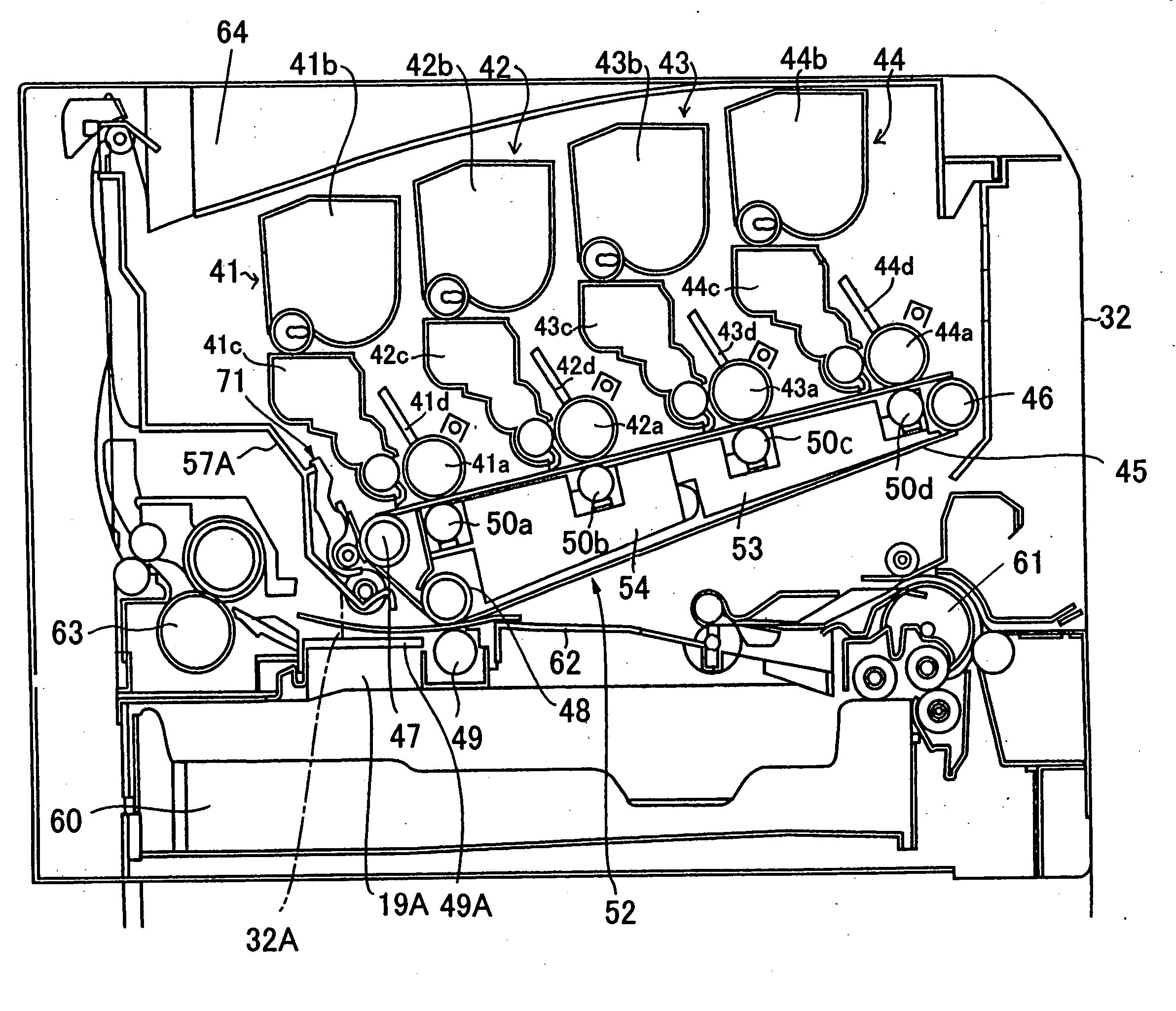
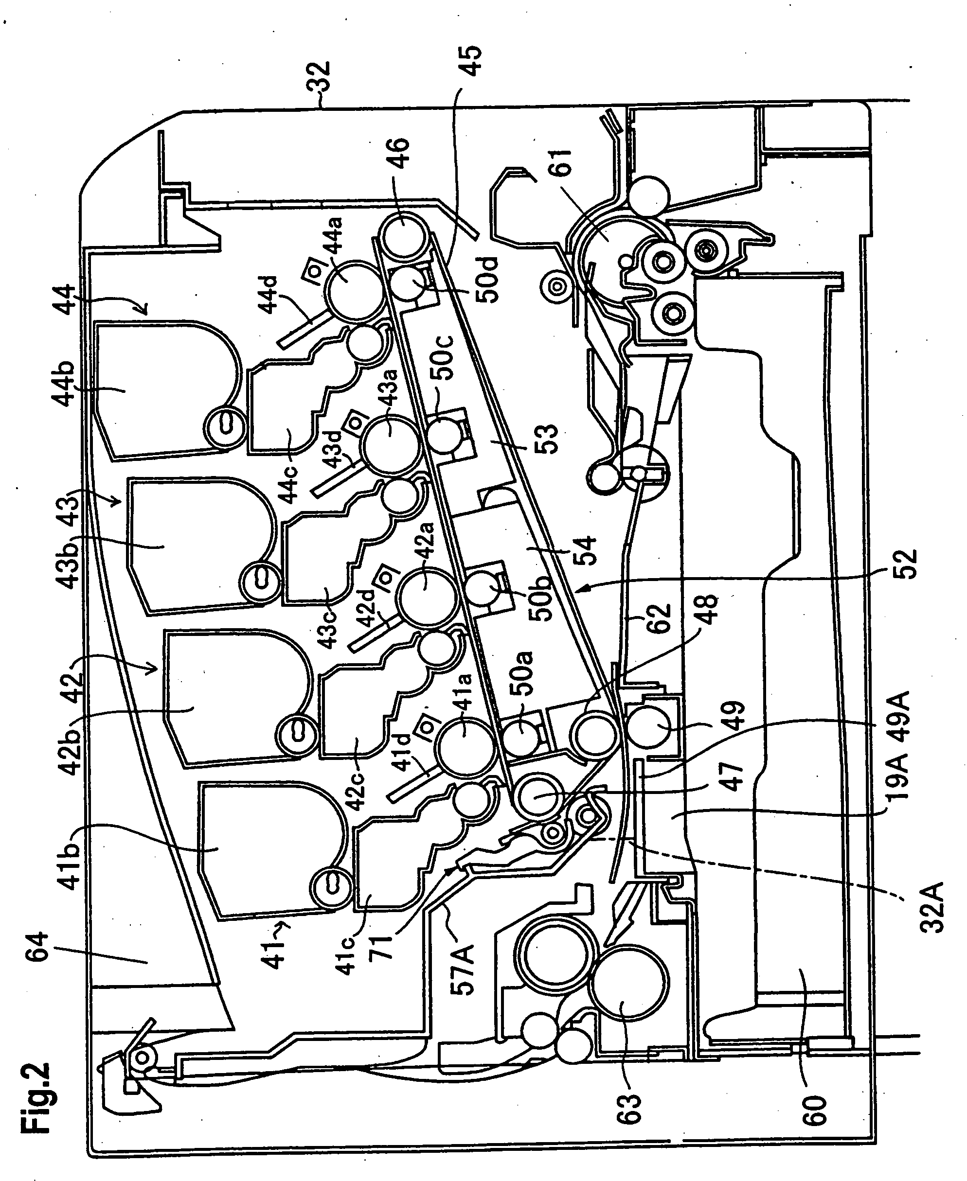
[0097] The image forming apparatus shown in FIGS. 2 and 3 consists of a plurality of image forming units 41-44. Image forming units 41-44 are composed of photosensitive body drums (image bearing bodies) 41a-44a, developing devices 41c-44c (not shown in FIG. 3) and exposing units 41d-44d (not shown in FIG. 3), respectively. Toner containers 41b-44b are also provided, respectively, for image forming units 41-44. Image forming units 41-44 may have a handle (not shown) for allowing ima...


PUM


Abstract

An image forming apparatus having a belt supporting frame for supporting an intermediate transfer belt is provided. The intermediate transfer belt is a multi-layered structure composed of at least an elastic layer on a substrate layer. When a percentage difference of a stretched length of an outer circumference of the intermediate transfer belt to an inner circumference thereof at a position of contact to the driving roller is A % and a percent difference of a length of stretched side of the belt driven and stretched by the driving roller to a length of non-stretched opposite side of the belt is B %, the intermediate transfer belt is configured so that ranges of A and A+B fall simultaneously into inequalities of 1<A<6 and 3<A+B<10.

Description

CROSS-REFERENCE TO RELATED APPLICATIONS [0001] This application is a divisional of application Ser. No. 10 / 280,134, filed Oct. 24, 2002.BACKGROUND OF THE INVENTION [0002] The present invention relates to an image forming apparatus by an electro-photography process such as a copying machine, a printer or a facsimile. More particularly, the present invention relates to an image forming apparatus which forms images utilizing an endless belt such as an endless intermediate transfer body. [0003] Generally, an electro-photographic image forming apparatus (hereinafter referred to as an image forming apparatus) which utilizes an endless belt of an intermediate transfer body (hereinafter referred to as an intermediate transfer belt) to form color images using an electro-photography process is known in the art. In the image forming apparatus, a plurality of image forming units are disposed along an intermediate transfer belt and a second transfer roller is disposed at the downstream of the ro...

Claims


Application Information

Patent Timeline
Patent Type & Authority Applications(United States)
IPC IPC(8): G03G15/01G03G15/16
CPCG03G15/1605G03G15/161G03G15/1685G03G15/0194G03G2215/0129G03G15/0136G03G2215/0119
Inventor OZAWA, YOSHIOKONISHI, HIDEHISA
Owner KYOCERA CORP
Why Eureka
Try Eureka