
Gas monitor

a monitor and gas technology, applied in the field of gas monitors, can solve the problems of high component cost, high production and adjustment cost, and limited performance of low signal level solutions, and achieve the effects of reducing the need for analogue amplifiers and analogue signal conditioning using discrete components, reducing the need for adjustment and trimming, and fewer discrete components

Inactive Publication Date: 2006-03-02
NORSK ELEKTRO OPTIKK
View PDF15 Cites 130 Cited by
  • Summary
  • Abstract
  • Description
  • Claims
  • Application Information

AI Technical Summary

Benefits of technology

[0039] A major advantage of this invention is that the need for analogue amplifiers and analogue signal conditioning using discrete compone

Problems solved by technology

This solution has limited performance at low signal levels.
The component cost as well as production and adjustment cost are also high.
The large number of discrete components, e.g. mixers, typically means that many parameters have to be tweaked or adjusted to achieve a satisfactory system performance, thus adding to the total cost of a gas measuring device.

Method used


Image

  • Gas monitor
  • Gas monitor
  • Gas monitor

Examples


Embodiment Construction

[0048] The invention will now be described in more detail with reference to the accompanying drawings where

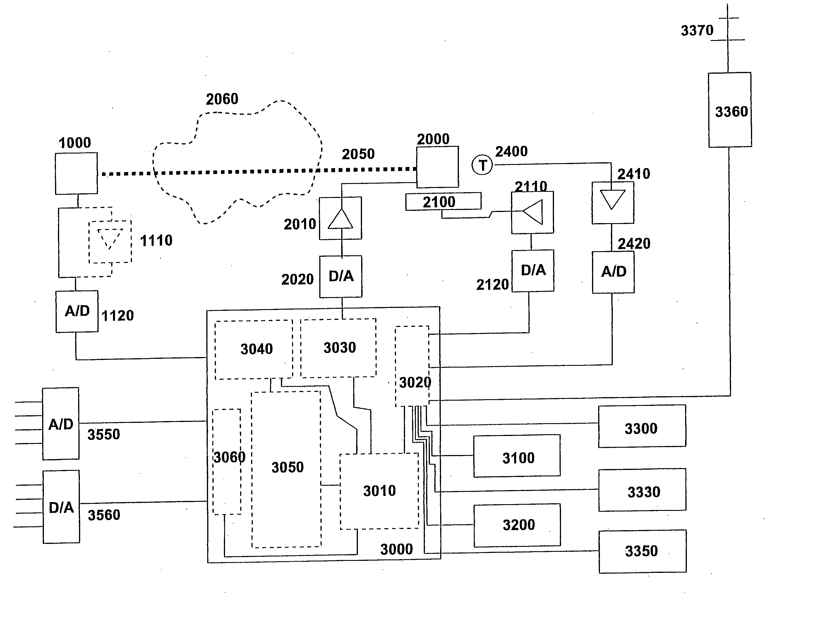
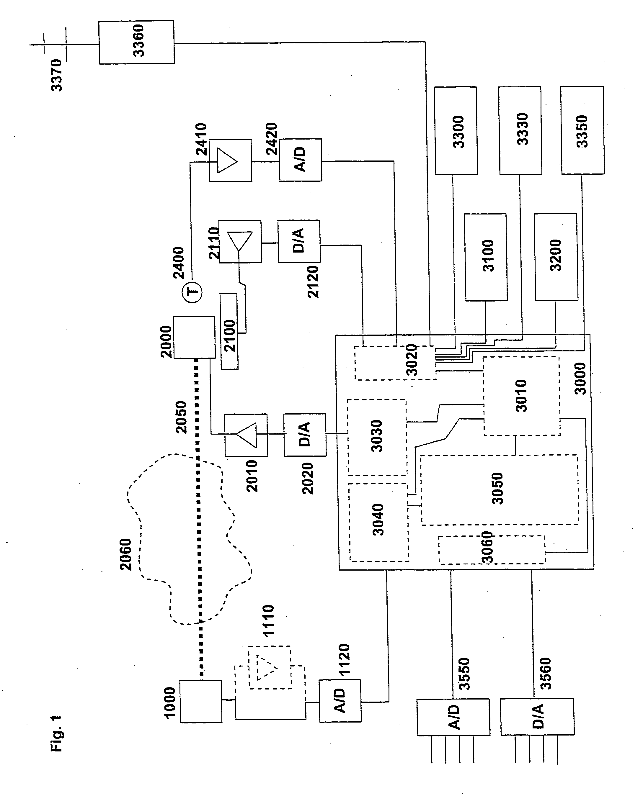
[0049]FIG. 1 illustrates a schematic view of an example embodiment of the gas monitor according to the present invention.

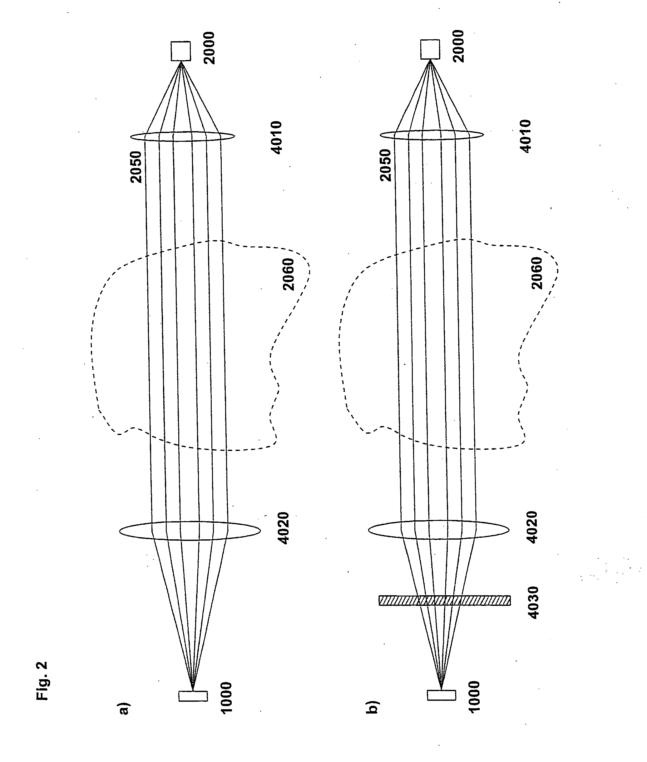
[0050]FIG. 2 illustrates the optical part of a gas monitor according to the invention.

[0051]FIG. 3a shows a monitor according to the invention with a conventional transmitter / receiver with the electronics split between the two units.

[0052]FIG. 3b depicts a monitor according to the invention using optical fibers for communicating digital signals between modules.

[0053]FIG. 3c illustrates a monitor according to the invention having a dual path or open path configuration.

[0054]FIG. 4 shows the details of the optical arrangement using a retro-reflector, dual path or open path design.

[0055]FIG. 5 is a schematic of a Wheatstone bridge circuit for the temperature measurement in the monitor according to the invention.

[0056]FIG. 6a illustrates an in-situ instal...


PUM


Abstract

Gas detection or monitoring apparatus mainly comprising, an optical source unit including a tunable diode laser, an optical detection unit including a light sensitive detector, the source and the detector being arranged so that light from the source propagates through a gas measurement volume prior to being received by the detector, and the source being adapted to scan the light wavelength across one or more expected absorption lines of gases in the measurement volume, a control and processing unit for control and modulation of the source and processing of the detected signal and for calculating at least one digital value representing (a) gas concentrations in the gas measurement volume, wherein said control and processing unit is coupled to the source via a digital-to-analogue (D / A) converter, and the detector output signal is coupled to the input of an analogue-to-digital (A / D) converter, and the output of the A / D converter is coupled to the processing unit.

Description

[0001] This invention in general relates to gas monitors used, for example, in the process industry. [0002] In particular this invention relates to improvements in detection and measurement of gas concentrations and gas emissions based on tuneable diode lasers. [0003] One of the most reliable measurement principles for continuous monitoring of gases is the use of spectroscopy. Most gases have one or more absorption lines in the ultra violet, visible or the infrared part of the spectrum. Many different spectroscopic techniques exist, but the use of single line spectroscopy utilizing tuneable diode lasers is probably the one giving best selectivity due to its high spectral resolution involving a low risk of interference from other gases. PRIOR ART [0004] One example of a gas monitor based on single line spectroscopy and optical filtering techniques is described in international patent publication WO9411713 to Norsk Hydro A.S. [0005] U.S. Pat. No. 5,637,872 to Tulip describes a gas det...

Claims


Application Information

Patent Timeline
IPC IPC(8): G01N21/17
CPCG01N21/031G01N2021/151G01N21/39
Inventor HAGENE, JON KRISTIANTORRING, HAVARDBJOROY, OVEAVETISOV, VIACHESLAV
Owner NORSK ELEKTRO OPTIKK
Learn More