
Axial air-gap electronic motor

a technology of electronic motors and axial air gap, which is applied in the direction of windings, magnetic circuit rotating parts, magnetic circuit shapes/forms/construction, etc., can solve the problems of troublesome wire connection work between the small stators, ineffective use of magnetic flux, and inability to effectively utilize magnetic flux. , to achieve the effect of convenient method

Active Publication Date: 2006-03-02
FUJITSU GENERAL LTD
View PDF2 Cites 49 Cited by
  • Summary
  • Abstract
  • Description
  • Claims
  • Application Information

AI Technical Summary

Benefits of technology

[0006] The present invention has been made to solve the above problems, and accordingly an object thereof is to provide an axial air-gap electronic motor in which work for assembling a stator can be performed efficiently.
[0008] According to this configuration, since the stator is configured so that the core members are arranged in a ring form and the shape thereof is held by the connecting member, not only the assembling workability is high, but also the wire connecting workability is very high.
[0010] According to this configuration, since the locking portion is provided in a part of the flange portion, the core members can be arranged and temporarily fixed by the connecting member easily without the need for complicated work.
[0012] According to this configuration, since the locking portion is constructed in a part of the insulator, the locking portion can be formed in advance when the insulator is molded, so that the electronic motor can be produced at a lower cost.
[0017] According to this configuration, by providing the positioning means in the flange portion of core member, positioning can be performed with great ease merely by putting the core member in the mold. Also, as the positioning means, positioning can be performed with great ease merely by providing the convex portion (or the concave portion) in the flange portion of core member and by forming the concave portion (or the convex portion), which coincides with the convex portion (or the concave portion) in the flange portion, in the mold.
[0019] According to this configuration, the height difference is provided between the insulator and the teeth surface, and the core member is positioned in the mold by utilizing the height difference, by which the core member can be positioned by an easier method.

Problems solved by technology

According to this axial air-gap electronic motor, although the stator can be assembled with ease merely by attaching the small stators to the bracket, a useless space is produced between the small stators, so that a magnetic flux cannot be utilized effectively.
Also, because of the construction in which small stators are attached to the disc-shaped bracket, wire connecting work between the small stators is troublesome.

Method used


Image

  • Axial air-gap electronic motor
  • Axial air-gap electronic motor
  • Axial air-gap electronic motor

Examples


Embodiment Construction

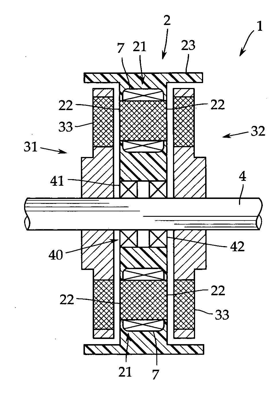
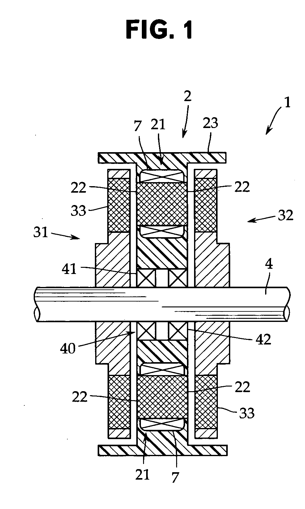
[0033] Embodiments of the present invention will now be described with reference to the accompanying drawings. FIG. 1 is a sectional view schematically showing an internal construction of an axial air-gap electronic motor in accordance with one embodiment of the present invention, and FIG. 2 is a perspective view showing a state in which core members are arranged in a ring form. The present invention is not limited to the embodiment shown in these figures.

[0034] This axial air-gap electronic motor 1 includes a stator 2 formed in a disc shape and a pair of rotors 31 and 32 disposed opposedly on both side surfaces of the stator 2 with a predetermined gap provided between the stator and the rotor. The rotors 31 and 32 are fixed coaxially on a rotor output shaft 4 for delivering a rotational driving force.

[0035] In this example, the axial air-gap electronic motor 1 is a permanent magnet electronic motor of a two rotor type having the rotors 31 and 32 on both side surfaces of the stato...


PUM


Abstract

There is provided an axial air-gap electronic motor in which work for assembling a stator can be performed efficiently. A locking protrusion 26 is provided on a flange portion 24 of core members 21a to 21i which are divided for each teeth 21 and are arranged in a ring form with the rotating shaft axis line being the center, and a connecting member 8 is fitted on the locking protrusion 26, by which the core members 21a to 21i are connected to each other in a ring form.

Description

TECHNICAL FIELD [0001] The present invention relates to an axial air-gap electronic motor in which a stator and a rotor are arranged opposedly with a predetermined gap along the axis line direction of a rotating shaft of the rotor. More particularly, it relates to an axial air-gap electronic motor having high assembling workability. BACKGROUND ART [0002] An axial air-gap electronic motor is an electronic motor in which a rotor is arranged opposedly on one side surface or on both side surfaces of a stator with a predetermined gap, and a feature thereof is that the thickness thereof in the axial direction of the rotating shaft can be decreased, namely, the electronic motor can be made flat as compared with a radial gap electronic motor of an inner rotor type etc. [0003] As described, for example, in Japanese Patent Application Publication No. 2000-253635, in the axial air-gap electronic motor, usually, a plurality of small stators in which a coil is wound on a stator iron core are man...

Claims


Application Information

Patent Timeline
IPC IPC(8): H02K1/22H02K1/18H02K1/00
CPCH02K1/14H02K21/24H02K3/524H02K1/182
Inventor KOJIMA, TOMONORITANNO, TOSHIAKITERAKUBO, HIDETAKASHINOHARA, TAKAYUKI
Owner FUJITSU GENERAL LTD
Learn More