
Systems, methods and apparatus of a magnetic resonance imaging magnet to produce an asymmetrical stray field

a magnetic resonance imaging and magnetic resonance imaging technology, applied in the field of magnetic resonance imaging systems, can solve the problems of difficult access to the area in the magnetic resonance imaging system where the imaging is carried out, the shape and size of the conventional mri system is not easy to accommodate the imaging of the hand, the elbow, the ankle or the knee,

Inactive Publication Date: 2006-02-23
GENERAL ELECTRIC CO
View PDF9 Cites 4 Cited by
  • Summary
  • Abstract
  • Description
  • Claims
  • Application Information

AI Technical Summary

Benefits of technology

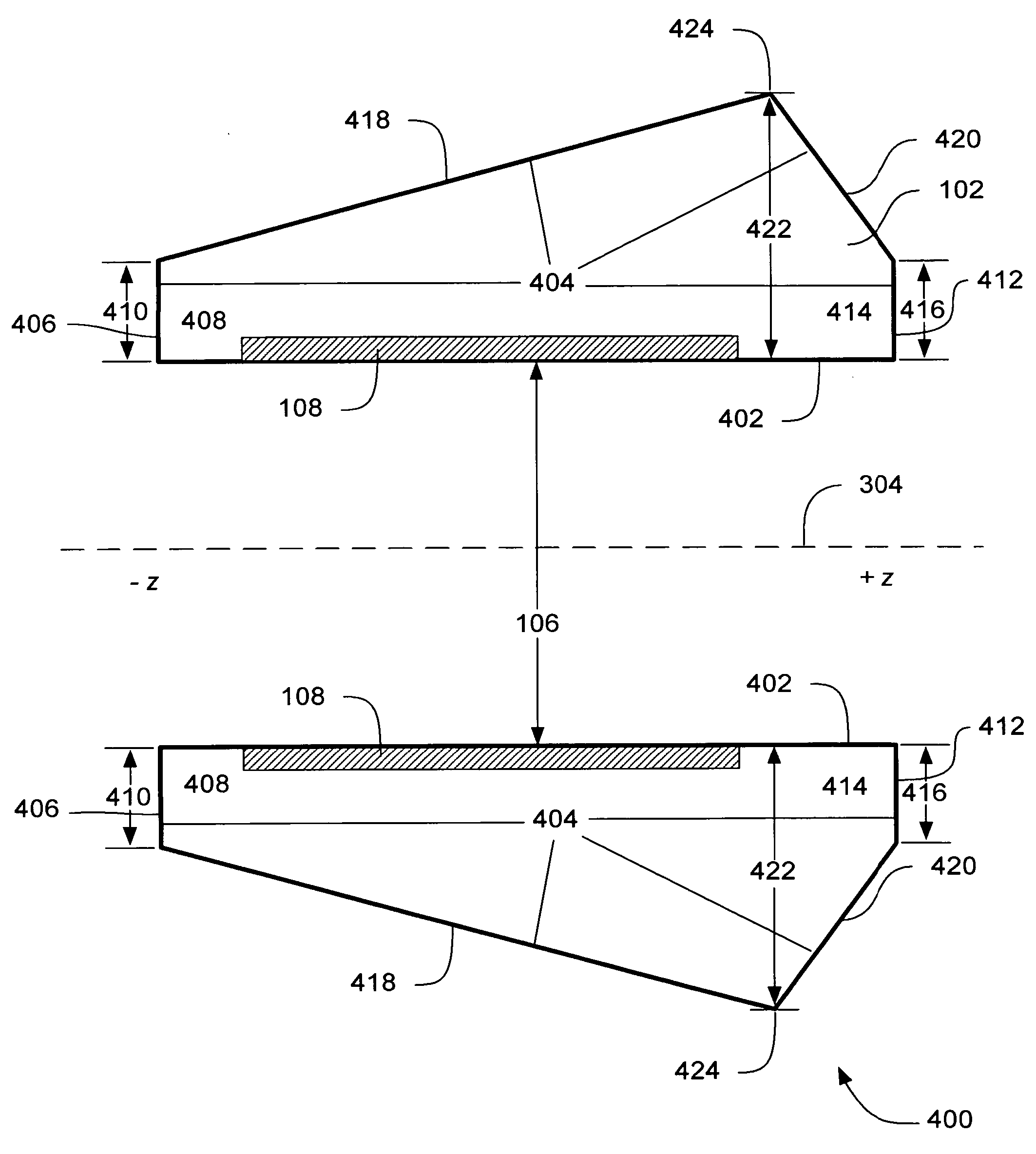
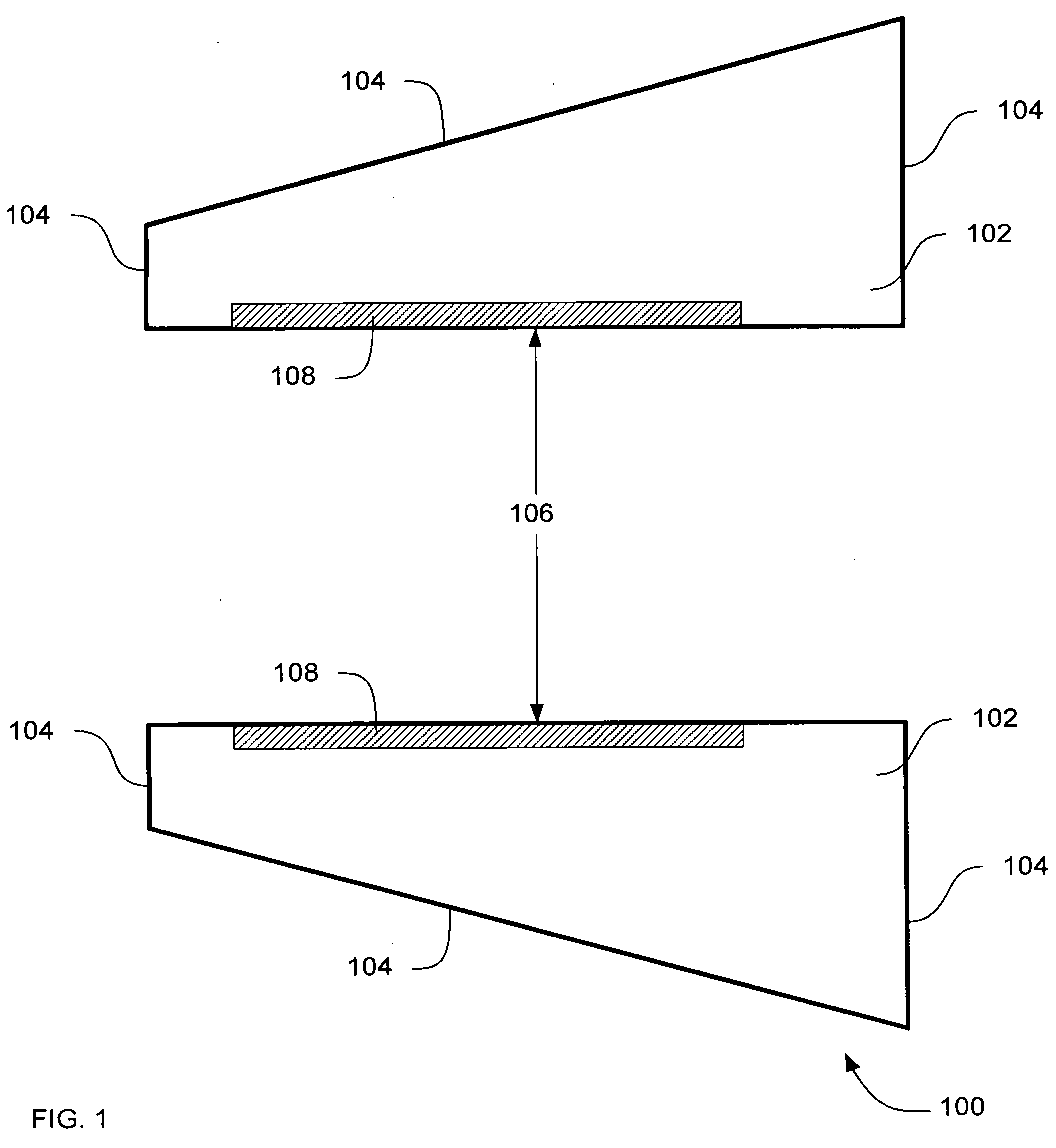
[0010] In one aspect, an apparatus to image a subject comprises a casing and at least one asymmetrical magnet disposed in the casing. The asymmetrical magnet provides an asymmetrical stray field that projects one portion of the stray field further towards a position where a patient access the imaging inner bore of the MRI, thereby solving the need in the art for an MRI system with that provides more comfortable access to a patient during imaging of an extremity of the patient while reducing hospital floor space requirements. In some further embodiments, an asymmetrically-shaped array of a plurality of magnetic coils further comprises an elongated shape in which an elongated portion of the elongated shape is furthest from where a patient would be located during operation of the magnetic resonance imaging apparatus, further reducing floor space requirements.
[0011] In another aspect, an apparatus to image a subject comprises a casing having a conically-shaped outer perimeter, the casing having an inner bore, and a plurality of magnetic coils positioned in the casing in close proximity to the inner bore. A narrow portion of the conically shaped outer perimeter is closer towards a position where a patient access the imaging inner bore of the MRI, thereby solving the need in the art for an MRI system with that provides more comfortable access to a patient during imaging of an extremity of the patient. The conical shape also provides a smaller volume of the casing, which solves the need in the art for reduced floor space requirements of MRI systems.
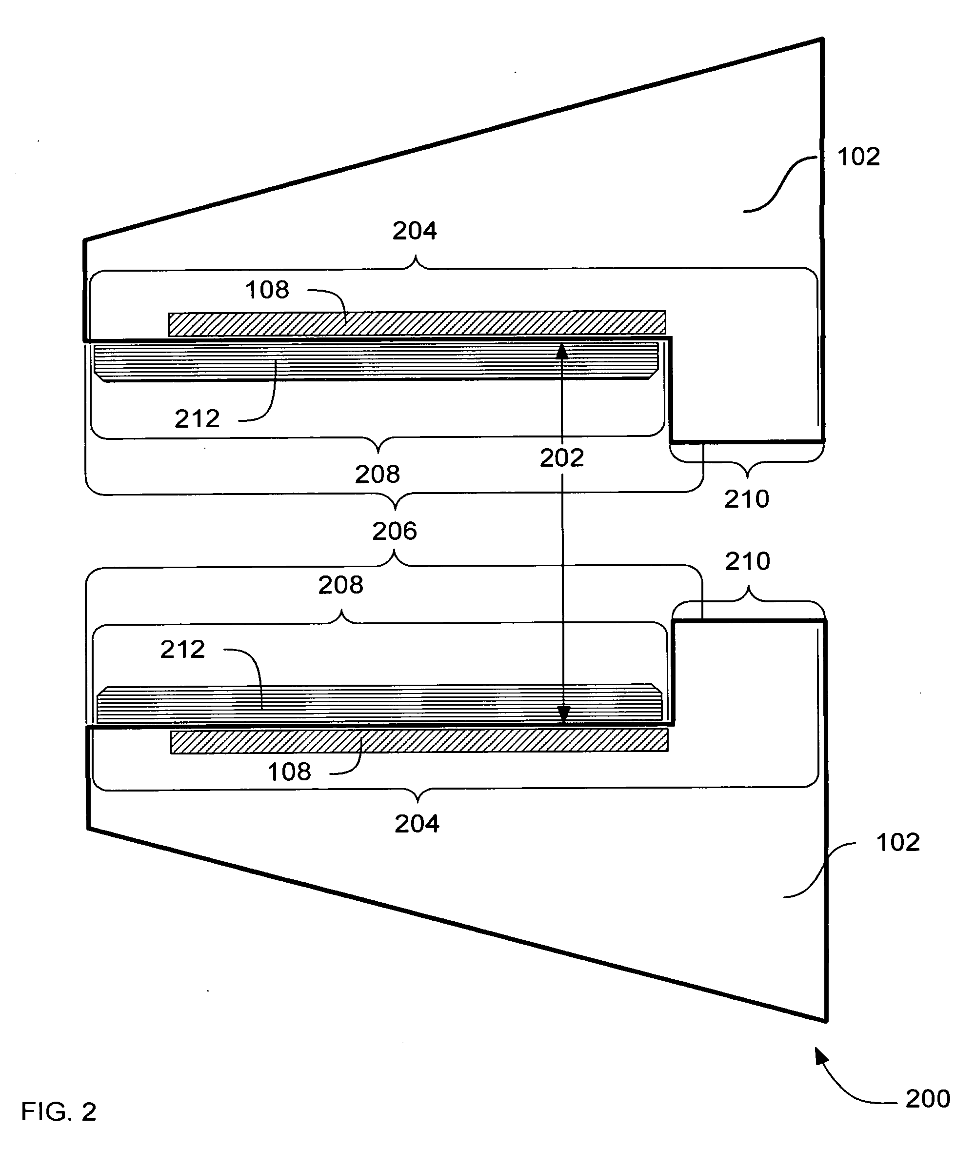
[0012] In yet another aspect, an apparatus to image a subject using magnetic resonance comprises a casing having an inner bore, the inner bore defining an inner diameter of the casing, wherein the inner diameter further comprises a stepped radius in which a wider portion of the inner diameter includes a gradient coil and the wider portion is furthest from where a patient would access the inner bore during operation of the magnetic resonance imaging apparatus. The stepped inner diameter provides an apparatus that supports insertion of a gradient coil from one end of magnet, while improving the length of a superconductor and the stray field.

Problems solved by technology

Conventional MRI systems do not accommodate many of the unique requirements of imaging of extremities such as hands, elbows and knees.
More specifically, conventional MRI systems have shapes and sizes that do not easily accommodate the imaging of a hand, a wrist, an elbow, an ankle or a knee.
Access is rather difficult to the area in the MRI system where the imaging occurs because of the large dimensions of a conventional MRI system.
The positions are often uncomfortable and aggravating for patients with minor health problems, and often difficult and / or painful for seriously injured patients, and in some instances, either physically impossible or physically harmful.
More specifically, the problem with the size and shape of conventionally shaped orthopedic MRI systems is that the front face of the MRI system is wide.
Another problem with the size and shape of conventional MRI systems is that the distance between the front face and the field of view is minimally sufficient, if at all sufficient, to allow the patient to extend their arm into the field of view from the outside of the MRI system.
For claustrophobic patients, this can be a traumatic experience.
In addition, the large size of conventional MRI systems requires a large floor space to in which to site the MRI system.
The large floor space is one aspect of conventional MRI systems that is not welcomed by medical facilities because of the high cost of each square foot of floor space.

Method used


Image

  • Systems, methods and apparatus of a magnetic resonance imaging magnet to produce an asymmetrical stray field
  • Systems, methods and apparatus of a magnetic resonance imaging magnet to produce an asymmetrical stray field
  • Systems, methods and apparatus of a magnetic resonance imaging magnet to produce an asymmetrical stray field

Examples


an embodiment

Methods of an Embodiment

[0076] In the previous section, apparatus of the operation of an embodiment was described. In this section, the particular methods performed by a processor of a magnetic resonance imaging (MRI) system, of such an embodiment are described by reference to a series of flowcharts.

[0077]FIG. 12 is a flowchart of a method 1200 of generating an image from electromagnetic resonance induced by a magnet with an asymmetric stray field according to an embodiment.

[0078] Method 1200 includes inducing 1202 electromagnetic resonance in a subject, using an asymmetric magnet that produces an asymmetric stray field. Method 1200 includes driving 1204 a gradient coil to spatially encode the image. Method 1200 also includes driving 1206 a gradient eddy current correction coil in the MRI. The coil compensates for the asymmetric eddy currents generated by the gradient coil in system 200, apparatus 500, 900 and 1000.

[0079] Method 1200 further includes receiving 1208 radio frequenc...


PUM


Abstract

Systems, methods and apparatus are provided through which in some embodiments a magnetic resonance imaging (MRI) system includes an asymmetrical magnet to generate an asymmetrical stray field that is particularly well suited to imaging limbs. In some other embodiments, a MRI system includes a conically-shaped casing that allows a patient to more readily access a field-of-view (FOV) in the interior of the MRI system during imaging of limbs. In some embodiments, a MRI system includes a stepped inner bore that has a stepped shape that focuses the FOV in an inner bore of the MRI system on a smaller area that is closer to where a patient accesses the FOV in the MRI that is particularly well suited to imaging a limb in the FOV.

Description

FIELD OF THE INVENTION [0001] This invention relates generally to magnetic resonance imaging systems, and more particularly to magnetic resonance imaging systems for orthopedic anatomic extremity imaging. BACKGROUND OF THE INVENTION [0002] Orthopedics is a medical specialty concerned with correction of deformities or functional impairments of the skeletal system, particularly, of the extremities and the spine, and associated structures, such as muscles and ligaments. For example, diagnosis and treatment of broken hand bones is a common practice in orthopedics. Because many orthopedic health problems are subcutaneous, imaging anatomy under the skin is a very important capability in orthopedics. Magnetic resonance imaging (MRI) is one imaging technique implemented in orthopedic diagnosis. [0003] Conventional MRI systems do not accommodate many of the unique requirements of imaging of extremities such as hands, elbows and knees. More specifically, conventional MRI systems have shapes a...

Claims


Application Information

Patent Timeline
Patent Type & Authority Applications(United States)
IPC IPC(8): G01V3/00G01R33/38G01R33/381G01R33/421
CPCG01R33/3806G01R33/421G01R33/381G01R33/38G01R33/3815A61B5/055
Inventor HAVENS, TIMOTHY JOHN
Owner GENERAL ELECTRIC CO
Learn More