
Geoplane calibration device and method based on spherical triangle geometric theory

A laser sweeper, spherical triangle technology, applied in the direction of measuring devices, instruments, etc., can solve the problems of lowering, occupying a large area, unable to calibrate the sweeping error, etc., to improve repeatability, reduce floor space requirements, and improve calibration accuracy Effect

Pending Publication Date: 2022-01-28
HENAN PROVINCE INST OF METROLOGY
View PDF0 Cites 1 Cited by
  • Summary
  • Abstract
  • Description
  • Claims
  • Application Information

AI Technical Summary

Problems solved by technology

[0008] In view of the above situation, in order to overcome the defects of the prior art, the present invention provides a laser leveling instrument calibration device and method based on spherical triangle geometry theory, using parallel light tube infinity simulation technology to solve the problem that the field method occupies a large area and the measurement is affected Difficulties with large influence of external factors, reduced floor space requirements, less environmental impact, improved repeatability of calibration results, and solved the problem that the laser leveling instrument cannot be placed in different placement states when calibrating the laser leveling instrument in the prior art Sweeping error calibration, and the device is added with a rotating and moving platform, using positive and negative 180° dual-position readings, and data processing based on the geometric principle of spherical triangles, which eliminates the vertical system error of the standard vertical plane and reduces the stability requirements for the device. , which improves the calibration accuracy of the device and makes up for the defects of low accuracy in the prior art

Method used


Image

  • Geoplane calibration device and method based on spherical triangle geometric theory

Examples


Embodiment Construction

[0027] The specific implementation manners of the present invention will be further described in detail below in conjunction with the accompanying drawings.

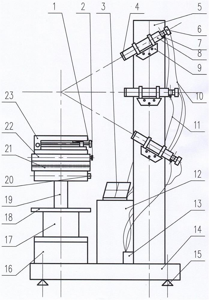
[0028] When this embodiment is in use, one end of the platform is provided with a lifting workbench, a 360° rotating workbench is fixed on the lifting workbench, and a translation workbench with a stroke of not less than 50mm is set up on the turntable, and the inclination range of the translation workbench is ±2.5mm. ° Slightly inclined workbench; the other end of the platform is equipped with a column, and three supports are installed on the column at three positions symmetrically distributed at 0° horizontally and ±30° inclined, and three long focal length parallel lights are erected on the three supports. The front end of each collimated light tube is equipped with a light-reducing filter group. The focal plane of the light tube is provided with a two-dimensional scale reticle. Behind the reticle is fixed an illuminat...


PUM


Abstract

The present invention provides a geoplane calibration device and method based on the spherical triangle geometric theory. According to the present invention, a collimator infinity simulation technology is adopted, the problems that a field method is large in occupied area and measurement is greatly influenced by the external factors, are solved, the data is processed according to the spherical triangle geometric theory, and a plumb system error of a standard vertical plane is eliminated. According to the technical scheme for solving the problems, the geoplane calibration device comprises a base, and is characterized in that a stand column is fixedly connected to the base, a workbench is arranged on the base on the side surface of the stand column and comprises a lifting table base, and a rotary workbench is connected to the lifting table base; a translation workbench is connected to the rotary workbench, and an inclined workbench is connected to the upper end of the translation workbench; light pipes which extend towards the workbench and are in same plane with a screw axis are fixedly connected to the positions, corresponding to the screw axis, of the stand column respectively, the axis focus of each light pipe coincides with the screw axis, and the included angle between every two adjacent light pipes is 30 degrees.

Description

technical field [0001] The invention relates to a calibration device, in particular to a calibration device and method for a laser leveling instrument based on spherical triangle geometry theory. Background technique [0002] The laser leveling instrument calibration device is a measurement standard used to calibrate the leveling error of the laser leveling instrument's horizontal and vertical three-dimensional planes. [0003] The current international standard ISO17123-6: 2012 (E) Optics and optical instruments —Field procedures for testing geodetic and surveying instruments —Part 6:Rotating lasers proposes a simple field calibration device with two rods and two scales, which requires a field of tens of meters , occupies a large area, the laser beam is strongly disturbed by airflow and light, the measurement accuracy is low, and it can only meet the leveling error measurement of the horizontal plane, with few functions; [0004] (2) The utility model invention ZL01212589....

Claims


Application Information

Patent Timeline
Patent Type & Authority Applications(China)
IPC IPC(8): G01C25/00
CPCG01C25/00
Inventor 张卫东陆进宇王广俊王冬梅苏清磊姚爽程鹏里聂金玲
Owner HENAN PROVINCE INST OF METROLOGY
Learn More