
Hybrid powered welder

a hybrid welder and power supply technology, applied in welding apparatus, manufacturing tools, electric heating, etc., can solve the problems of difficult use of fuel cells as power sources for welders, and achieve the effects of less noise, increased versatility, and increased energy efficiency

Active Publication Date: 2006-02-23
LINCOLN GLOBAL INC
View PDF60 Cites 126 Cited by
  • Summary
  • Abstract
  • Description
  • Claims
  • Application Information

AI Technical Summary

Benefits of technology

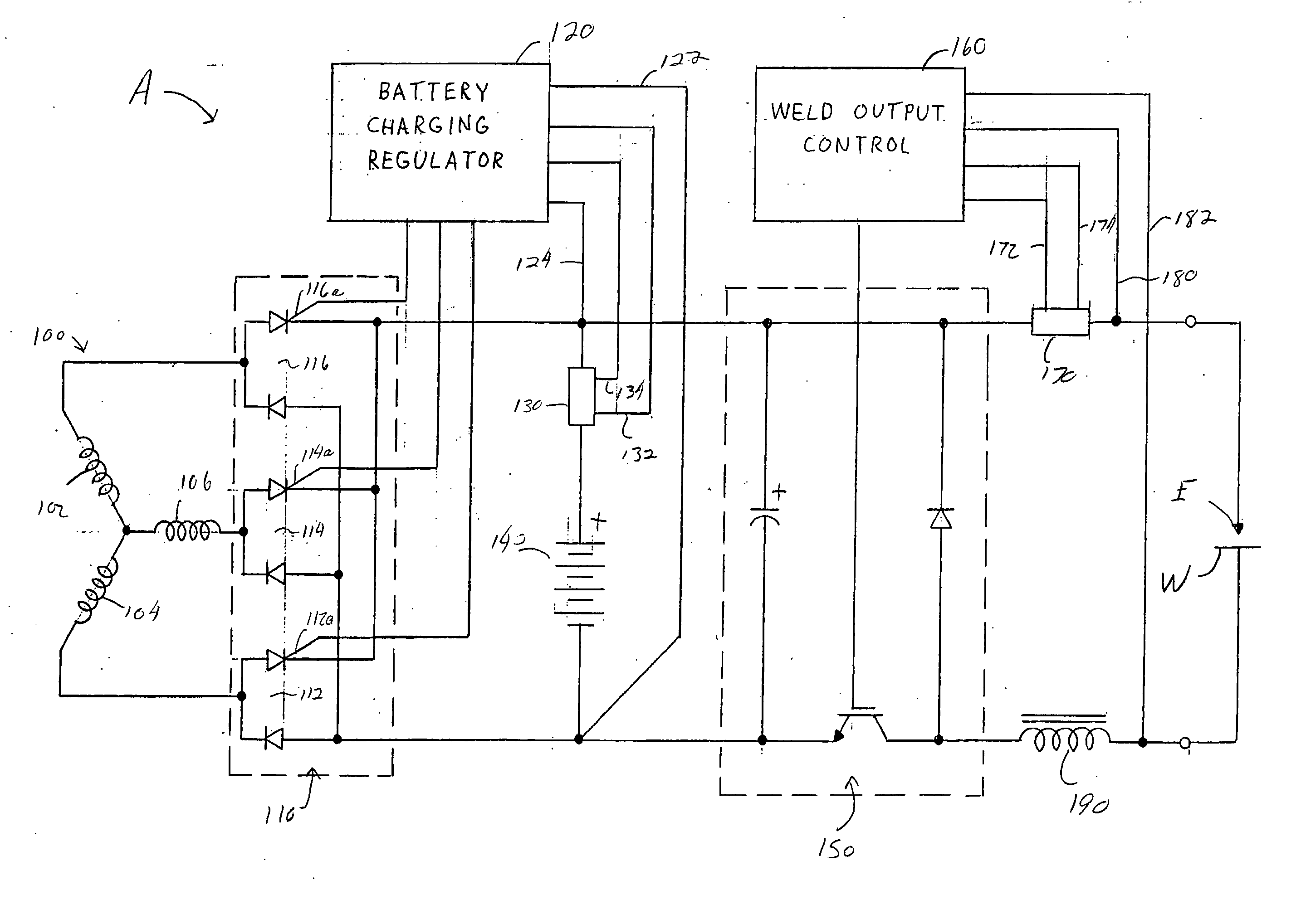
[0004] The present invention is an improvement in electric arc welder technology. The invention is particularly directed to electric arc welders having hybrid energy sources and the advantages associated with the use of such hybrid energy sources. The hybrid energy source includes one or more battery power sources and one or more non-battery power sources. The battery power source can be any type or combination of energy storage device. Typically the battery power source is formed from a single battery or multiple batteries; however, one or more other energy storage devices (e.g., capacitor, inductor, fly wheel, etc.) can be combined with and / or be used as an alternative to one or more batteries. The battery power source is typically rechargeable. When batteries are included in the battery power source, the same type of battery is typically used; however, this is not required. The non-battery power source typically includes an electric generator that is driven by a fuel-powered engine; however, the non-battery power source can alternatively include, but is not limited to, one or more fuel cells, solar cells, power grid (e.g., an electric outlet, etc), etc. The electric arc welder typically includes one battery power source and one non-battery power source; however, multiple battery power sources and / or multiple non-battery power sources can be used. If multiple non-battery power sources are used by the electric arc welder, the multiple non-battery power sources are typically different; however, this is not required. The use of a hybrid energy source in an electric arc welder provides several advantages. These advantages include, but are not limited to, the use of smaller fuel powered engines to drive an electric generator, increased energy efficiencies, increased versatility in using the electric arc welder, less noise, less pollution, less weight, small size, reduced cost, etc.

Problems solved by technology

Although fuel cells have been proposed for use in welders, the optimum transient characteristics of the fuel cells made the fuel cells difficult to use as a power source for a welder.

Method used


Image

  • Hybrid powered welder
  • Hybrid powered welder
  • Hybrid powered welder

Examples


Embodiment Construction

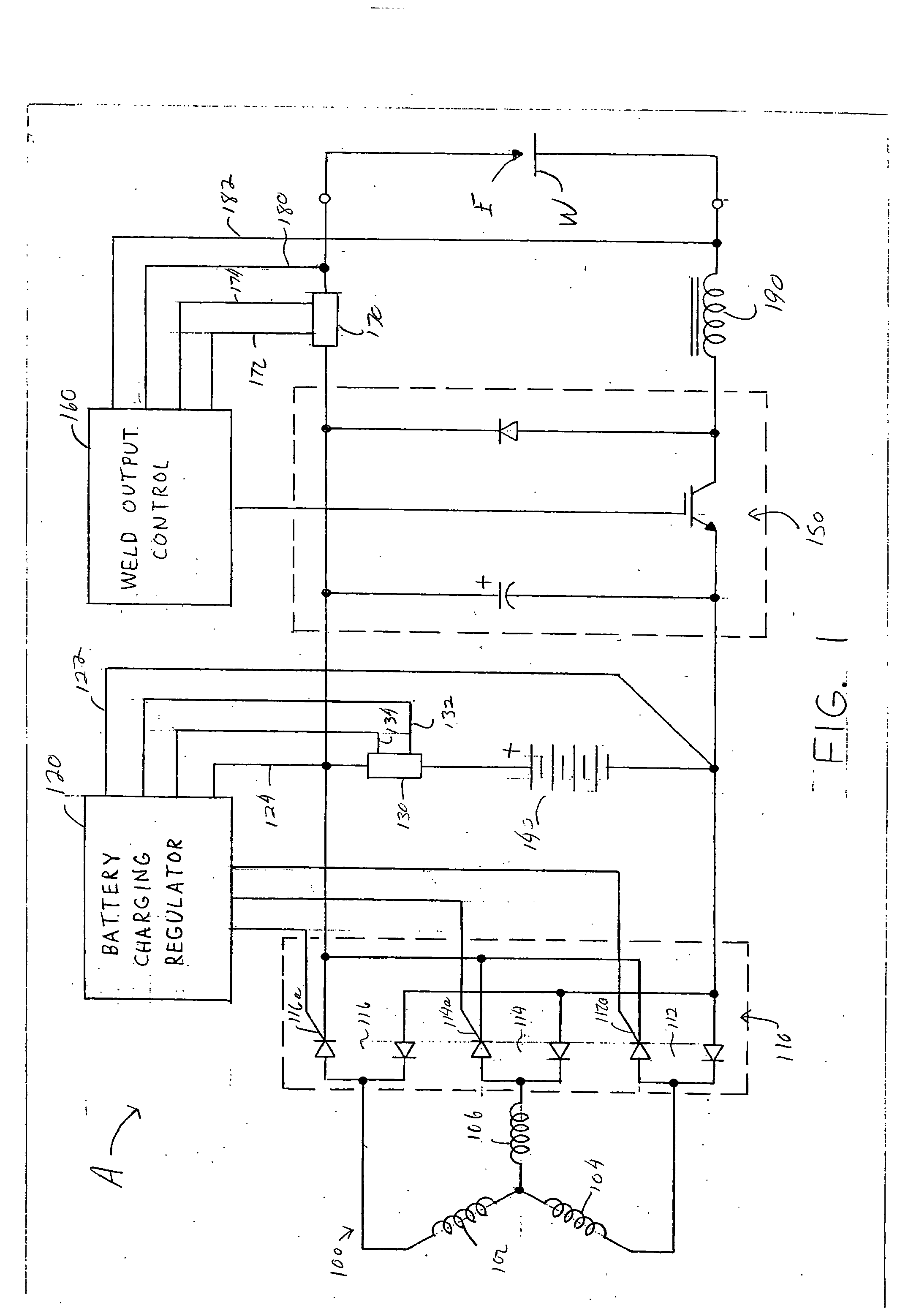
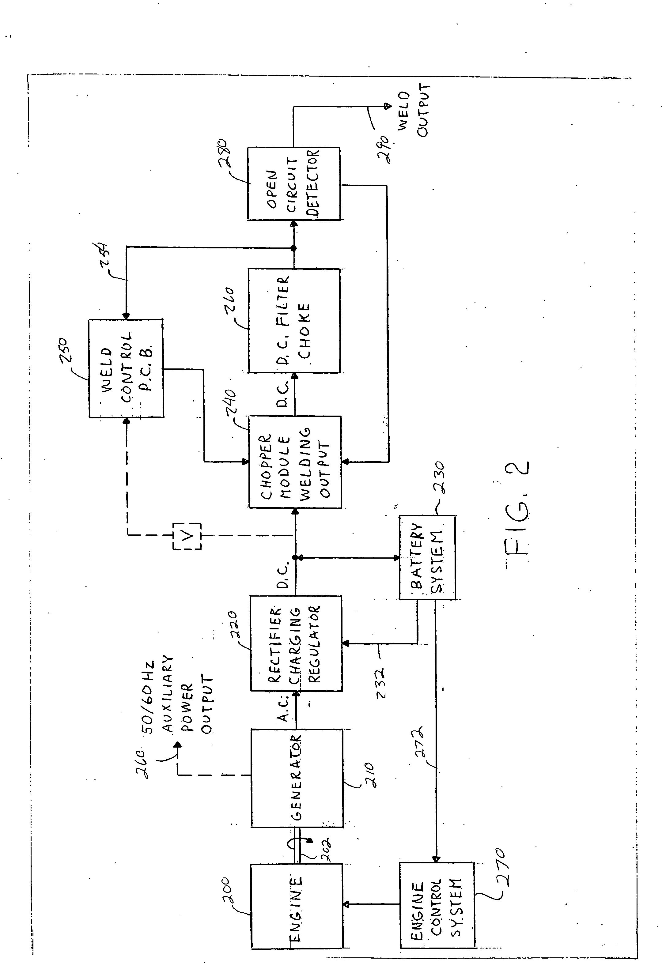
[0029] Referring now to FIGS. 1 and 2 wherein the showings are for the purpose of illustrating the preferred embodiments only and not for the purpose of limiting same, there is illustrated an electric arc welder that includes a hybrid energy source. The hybrid energy source of the present invention can be substituted for most, if not all, power sources currently used in engine welders. Currently, engine welders are powered by a gasoline powered or a diesel powered engine used to drive an electric generator that creates a current used to form an electric arc during a welding procedure. The size of the engine and electric generator used in the engine welder is dependant on the maximum power rating of the engine welder. The engine and electric generator used in prior engine welders must be of sufficient magnitude to supply the maximum power rating of the engine welder at any time, irrespective of the type of duty cycle of a particular welding operation. As a result, these past engine w...


PUM

PropertyMeasurementUnit
Currentaaaaaaaaaa
Poweraaaaaaaaaa
Electric chargeaaaaaaaaaa

Abstract

An electric arc welder that includes a energy storage device and non-battery power source for the formation of an electric arc. The welder also includes battery charging circuit that controls the charging of the energy storage device by the non-battery power source. The non-battery power source can include an engine driven electric generator, power grid or a fuel cell.

Description

[0001] The invention relates to the art of electric arc welding and more particularly to an electric arc welder powered by a plurality of different energy sources. BACKGROUND OF THE INVENTION [0002] Electric arc welders that generate more than 100 amps of welding current typically require a fuel-powered engine to drive an electric generator which in turn generates the required current for a welding operation. The size of the engine and electric generator is dictated by the maximum welding output rating of the welder. For instance, a welder that is rated to generate a 300-amp, 33.3 volt arc requires 10 kilowatts of power to generate such an arc. The engine in such a welder must have a large enough horse power to drive an electric generator to generate at least 10 kilowatts of power so as to supply the maximum welding output rating of the welder at any given time. The cost associated with large engines and associated electric generators significantly increases when large welding curre...

Claims


Application Information

Patent Timeline
IPC IPC(8): B23K9/10
CPCB23K9/1006B23K9/1081B23K9/1075
Inventor MATTHEWS, WILLIAM T.MUTER, BRYCESTUPCZY, FRANK M.
Owner LINCOLN GLOBAL INC
Learn More