
Solar distilling apparatus for alcohol

Inactive Publication Date: 2006-02-23
ROAN TONY +1
View PDF7 Cites 27 Cited by
  • Summary
  • Abstract
  • Description
  • Claims
  • Application Information

AI Technical Summary

Benefits of technology

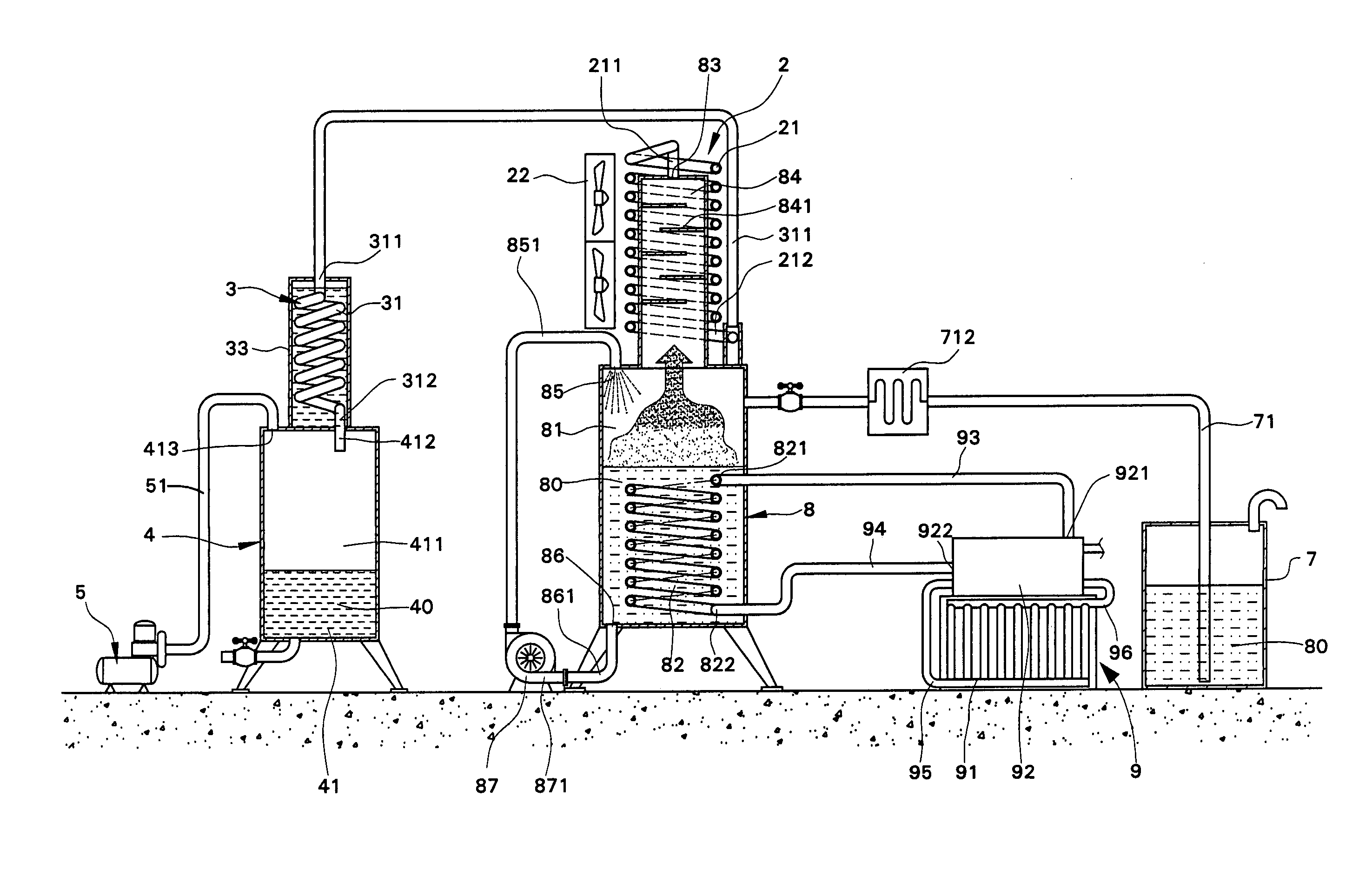
[0009] In accordance with an aspect of the present invention, a distilling apparatus for alcohol comprises an evaporation tank including a compartment for receiving fermented alcoholic liquid. A heating tube is mounted in the compartment for heating the fermented liquid into steam. A condensing device is communicated with the evaporation tank for receiving and condensing steam from the evaporation tank. A collecting tank is communicated with the condensing device for collecting conden

Problems solved by technology

Fermented liquids such as alcohol and vinegar without distillation contain impurities and may continue to ferment and thus become sour.
However, the resultant alcohol is not pure, and the alcohol concentration is not uniform throughout the distillation procedure.
Further, when the level of the alcoholic liquid in the distillation column is lowered to be approximately the same as that of a heater as a result of evaporation, the alcoholic liquid adjacent to the heater are heated at high temperature and thus generates a smell of char.
Further, the alcoholic liquid obtained from distillation could not be rapidly cooled such that the concentration of the alcoholic liquid is lowered.
Although continuous type distilling apparatuses have been used to improve the distilling efficiency, the structures and the procedures are complicated, leading to high cost and inconvenient maintenance and operation.
Further, the high heat for vaporizing the fermented alcoholic liquids burns the residue and impurities at the bottom of the fermented alcoholic liquid, adversely affecting the flavor.
Further, the high heat means consumption of a considerable amount of energy.

Method used


Image

  • Solar distilling apparatus for alcohol
  • Solar distilling apparatus for alcohol
  • Solar distilling apparatus for alcohol

Examples


Embodiment Construction

[0021] Referring toFIG. 1, a distilling apparatus for alcohol in accordance with the present invention comprises an evaporation tank 8 including a compartment 81 for receiving fermented alcoholic liquid 80. A heating tube 82 is provided in the compartment 81. In this embodiment, the heating tube 82 is helical and includes a first end 821 into which hot water flows and a second end 822. Located above the compartment 81 is a steam chamber 84 with a steam outlet 83. A plurality of separating plates 41 are alternately disposed in the steam chamber 84 to provide a plurality of vertically spaced and mutually communicated subchambers (not labeled) that define a winding path for the steam.

[0022] A circulating device 87 includes a circulating pump 871 that is connected to the compartment 81 via a tube 851. The tube 851 is connected to a refilling port 85 in a top wall delimiting the compartment 81. An outlet 86 is defined in a bottom wall delimiting the compartment 81 and communicated with ...


PUM

PropertyMeasurementUnit
Temperatureaaaaaaaaaa
Concentrationaaaaaaaaaa

Abstract

A distilling apparatus for alcohol includes an evaporation tank having a compartment for receiving fermented alcoholic liquid. A heating tube is mounted in the compartment for heating the fermented liquid into steam. A condensing device is communicated with the evaporation tank for receiving and condensing steam from the evaporation tank. A collecting tank is communicated with the condensing device for collecting condensed liquid from the condensing device. A negative pressure creating device creates a negative pressure in the evaporation tank, allowing the fermented alcoholic liquid in the evaporation tank to evaporate at a low temperature. A solar energy collecting device includes a solar energy collector and a water tank containing water heated by the solar energy collector. Hot water in the water tank flows into the heating tube for heating the fermented alcoholic liquid in the evaporation tank.

Description

BACKGROUND OF THE INVENTION [0001] 1. Field of the Invention [0002] The present invention relates to a distilling apparatus for alcohol. In particular, the present invention relates to a solar distilling apparatus for alcohol such as liquors, wines, etc. [0003] 2. Description of the Related Art [0004] Fermented liquids such as alcohol and vinegar without distillation contain impurities and may continue to ferment and thus become sour. For a fermented alcoholic liquid, distillation is required to remove impurities, to increase the alcoholic concentration, and to improve the flavor. [0005] As well known in the art, in addition to improvement in quality, fermented alcoholic liquids can be preserved for a longer time after distillation. In the past, alcohol makers without professional distilling equipments used in wine factories utilized ordinary water distilling apparatuses to distill the fermented alcoholic liquids. However, the resultant alcohol is not pure, and the alcohol concentra...

Claims


Application Information

Patent Timeline
IPC IPC(8): B01D5/00B01D3/10
CPCB01D1/0035B01D1/0047B01D1/0094B01D1/02B01D5/009B01D3/10B01D5/0006B01D5/0036B01D3/003Y02A20/212
Inventor ROAN, TONYROAN, JING-JYE
Owner ROAN TONY
Learn More