Variable displacement pump

a variable displacement, pump technology, applied in the direction of machines/engines, positive displacement liquid engines, liquid fuel engines, etc., can solve the problems of increasing the energy loss amount in a running state with great discharge flow rate, increasing the cost remarkably, and increasing the energy loss amoun

Inactive Publication Date: 2006-02-16
HITACHI ASTEMO LTD
View PDF9 Cites 7 Cited by
  • Summary
  • Abstract
  • Description
  • Claims
  • Application Information

AI Technical Summary

Benefits of technology

[0029] The present invention has further improvements on the variable displacement pump disclosed in JP-A-2002-98060. It is an object of the invention to provide a variable displacement pump in which a passage hole is made unnecessary, which is formed inside the pump body or in the adapter ring and connects the control valve and the second fluid pressure chamber, without impairing the restorability to the side for increasing the volume of pump chamber. The number of working steps is decreased. No high pressure is applied on the second fluid pressure chamber even momentarily. The pump can be used for higher pressures without increasing the size of the pump body.
[0031] In the variable displacement pump according to the invention, a pressure on the pump suction side is introduced into the second fluid pressure chamber at any time by dispensing with the oil passage from the control valve to the second fluid pressure chamber, whereby no high pressure is applied, vibration sound due to internal leakage or pulsation is improved, and it is unnecessary to increase the size of the pump body for greater strength. And to return the cam ring in a direction of maximizing the pump volume, an internal force of the cam ring, is set in the return direction, in addition to a spring force, whereby the cam ring can be returned in stable and rapid operation.
[0035] According to the above inventions, by introducing a discharge pressure between the inner and outer seal rings provided on one plate, the plate, the cam ring, the rotor, the adapter ring and the discharge opening are pressed onto the other plate, so that the side clearance is reduced as the pump discharge pressure is higher, thereby preventing the pump efficiency from decreasing due to internal leakage.
[0037] According to the above invention, the seal rings made of resin are supported from the back side by high pressure oil introduced into the concave portion, whereby the blow-by phenomenon can be prevented.

Problems solved by technology

The variable displacement pump 1 according to the related art having the above constitution has a problem that the energy loss amount is increased in a running state with great discharge flow rate, and it is found that this problem is caused by leakage of the pressure oil.
Hence, to make up for this amount of leakage, the engine speed must be increased to increase the discharge flow rate, resulting in the greater energy loss amount as previously described.
However, to adopt this structure, the front body 4 must be divided and formed at as high a precision as the adapter ring 9, increasing the costs remarkably.
Also, in the variable displacement pump 1 according to the related art, a discharge pressure is always applied to the second fluid pressure chamber 22 during the period of low rotating speed, resulting in a problem that the pump body 2 must be formed securely and increased in size.

Method used


Image

  • Variable displacement pump
  • Variable displacement pump
  • Variable displacement pump

Examples


Embodiment Construction

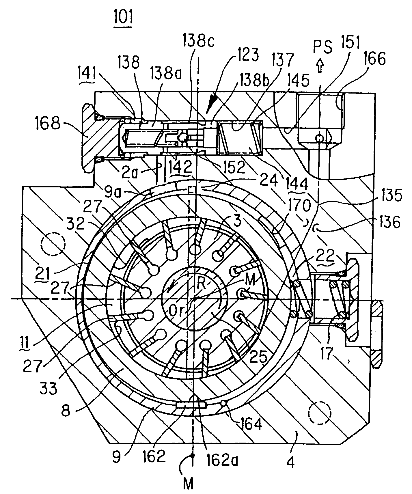
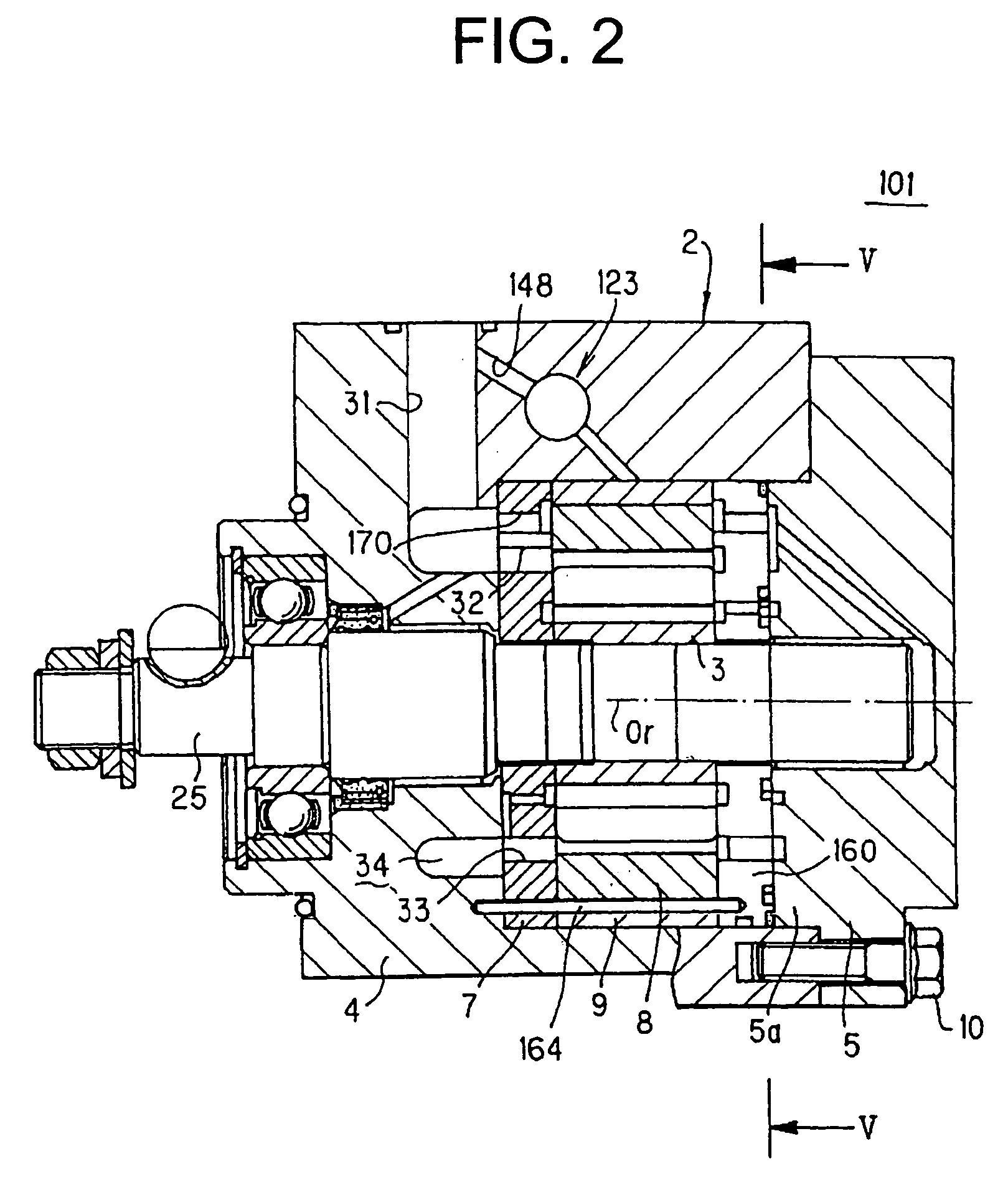
[0051] The preferred embodiments of the present invention will be described below with reference to the accompanying drawings. FIG. 1 is a cross-sectional view of a variable displacement pump according to one embodiment of the present invention, taken perpendicularly to an axial line of a drive shaft. FIG. 2 is a cross-sectional view of the variable displacement pump taken along the axial line of the drive shaft. The same or like parts are designated by the same numerals as those of the constitution according to the related art as previously described and shown in FIGS. 9 to 12, and not detailed anymore.

[0052] This variable displacement pump (numeral 101 as a whole) is employed as a hydraulic pressure supply source of a power steering device for the automobile, in which a motive power of an engine, not shown, is transmitted to a drive shaft 25 to rotate a rotor 3. In this embodiment, the drive shaft 25 and the rotor 3 are rotated in a counterclockwise direction, as indicated by an ...


PUM


Abstract

Within a cam ring (8), a rotor having a plurality of vanes (27) is eccentrically disposed. A metering orifice (136) is provided halfway on a discharge passage (135) of pressure fluid discharged from the pump, and a control valve is activated due to a pressure difference between the upstream and downstream sides of the metering orifice (136). A fluid pressure of the first fluid pressure chamber (21) is controlled by activation of the control valve (123). The second fluid pressure chamber (22) is shut off from the control valve (123) to introduce a pressure on the suction side at any time. To return the cam ring (8) in a direction of expanding a pump chamber (11), an internal pressure of the cam ring (8) is applied in the return direction.

Description

[0001] This is a divisional of application Ser. No. 10 / 359,279 filed Feb. 6, 2003. The entire disclosure(s) of the prior application(s), application number(s) Ser. No. 10 / 359,279 is hereby incorporated by reference. [0002] The present disclosure relates to the subject matter contained in Japanese Patent Application No. 2001-263663 filed on Aug. 31, 2001, which are incorporated herein by reference in its entirety.BACKGROUND OF THE INVENTION [0003] 1. Field of the Invention [0004] The present invention relates to a variable displacement pump for use as a hydraulic pressure supply source for an automobile power steering device, for example. [0005] 2. Description of the Related Art [0006] A variable displacement pump according to the related art of this kind is well known in which the discharge amount flow rate is controlled by increasing or decreasing the volume of a pump chamber, as disclosed in JP-A-6-200883, for example. Referring to FIGS. 9 to 12, the variable displacement pump dis...

Claims


Application Information

Patent Timeline
Patent Type & Authority Applications(United States)
IPC IPC(8): F01C20/18B62D5/065F04B1/06F04C2/344F04B17/00F04B49/00F04C14/22F04C15/00
CPCF04C14/226
Inventor UCHINO, KAZUYOSHI
Owner HITACHI ASTEMO LTD
Why Eureka
Try Eureka