Single-use long-life faucet-mounted water filtration devices
a technology of water filtration device and single-use, which is applied in the direction of filtration separation, separation process, treatment involving filtration, etc., can solve the problems of not having removable or replaceable parts yet providing long life operation, and achieves convenient use, long life operation, and small size
- Summary
- Abstract
- Description
- Claims
- Application Information
AI Technical Summary
Benefits of technology
Problems solved by technology
Method used
Image
Examples
first embodiment
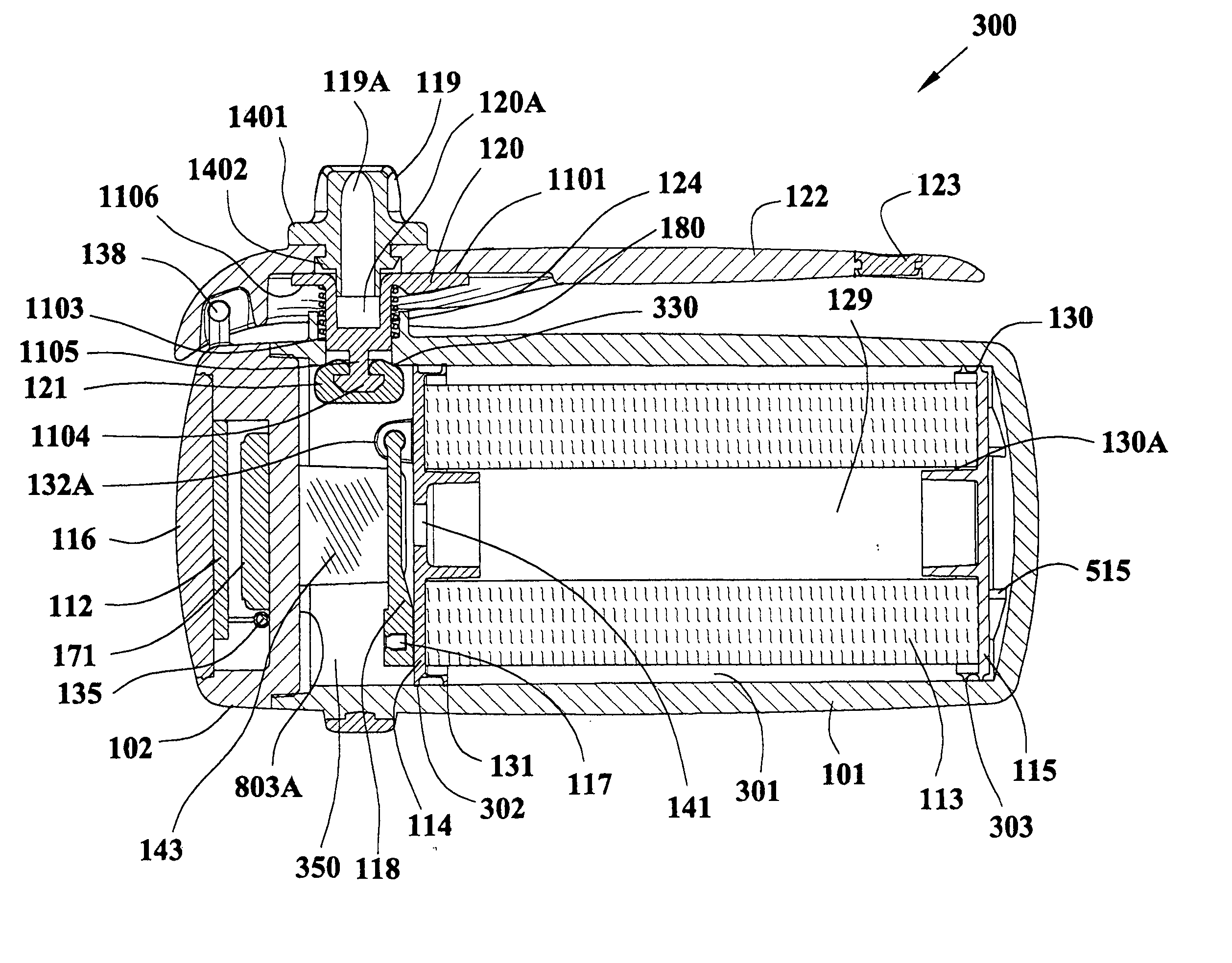
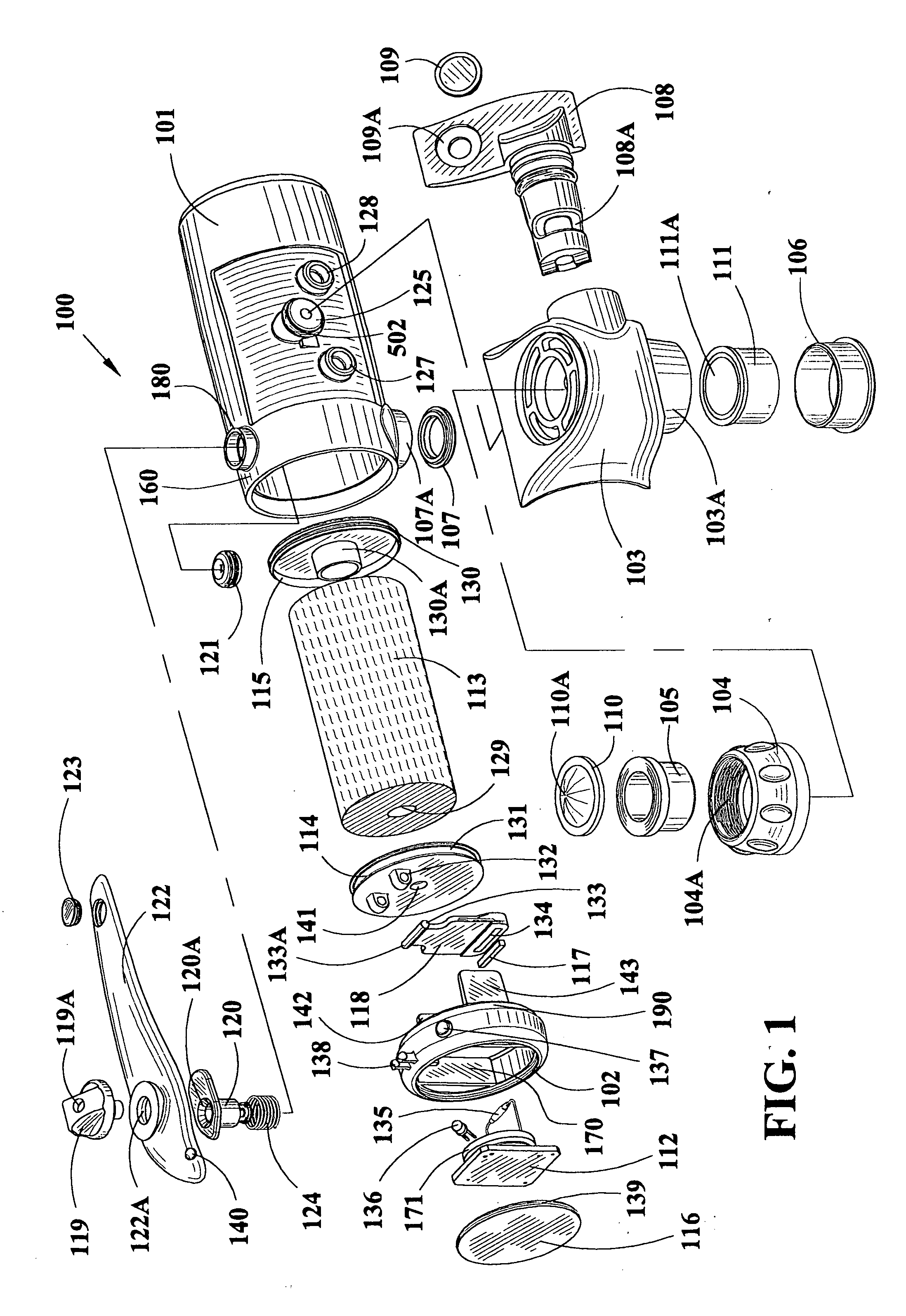
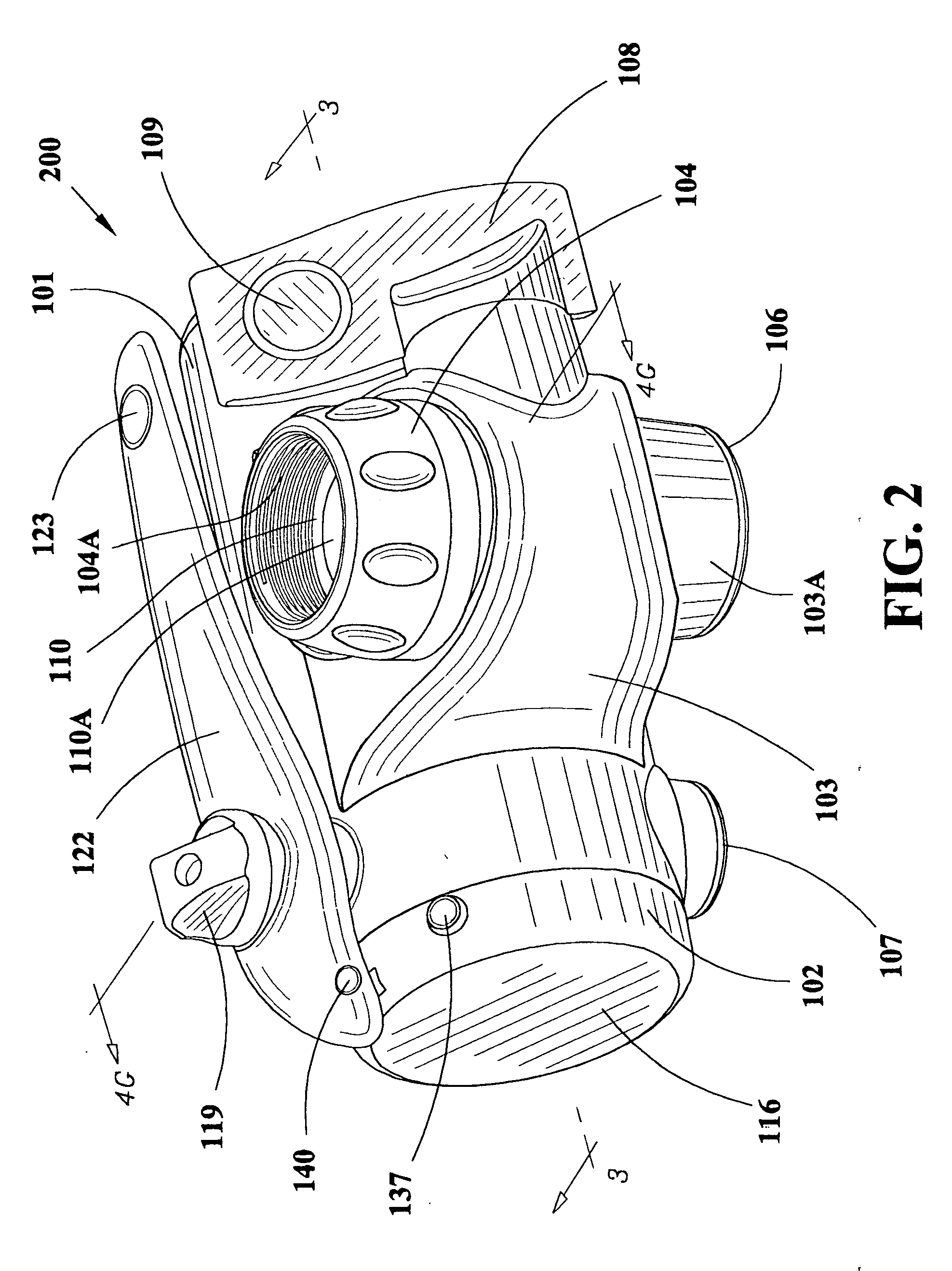
[0105] Referring to FIG. 1, an exploded assembly view of the water filtration device 100, the various components of the single-use faucet mounted water filter are shown. Filter 113 is illustrated having a longitudinal bore 129 therethrough. Filter 113 is illustrated without a filter pre-wrap in this view but such a pre-wrap 495 is specifically within the scope of this invention and is illustrated in FIGS. 4G and 4H. The filter is preferably a carbon block but may be a fiber bundle or granular activated carbon. Further, the carbon block may include bacteriastic materials, ion exchange resins and zeolites to assist in its filtration activity. End caps 114 and 115 are affixed to said filter with a hot melt adhesive applied to the entire mating surfaces of end caps 114 and 115 including but not limited to the dowel portions thereof such as dowel 130A on right end cap 130. Once filter 113 is affixed to end caps of filter 114, 115, the subassembly is inserted into the filter housing 101. ...
second embodiment
[0152]FIG. 18 is a perspective view 1800 of the front housing of the FIG. 18 employs reference numerals like FIG. 4. FIG. 18A is a cross-sectional view taken along the lines 18A-18A of FIG. 18. Reference numeral 1801 indicates the wall to which the collar lock 1505 is welded and reference numeral 1804 indicates the floor upon which the collar lock 1804 sits at the time it is welded. Mold recesses 1802 are from the molding process. Groove or recess 1816 receives the seal from the valve 108. Cavity 1831 receives the valve 108. Referring to FIG. 18A, stop 1807A is illustrated which engages ridges 602 on valve 108. Stop 1807A is also illustrated in FIG. 18B, a cross-sectional view taken along the lines 18B-18B of FIG. 18. Tapered bore 1812 is illustrated by the circular lines in FIG. 18A.
[0153] Bore 1822 includes stepped portions 1813 and 1829. Inlet 1808 is shown leading to valve cavity 1831. Outlet 1814 and outlet 1809 are also shown in FIG. 18A. When valve 108 is positioned as illus...
PUM
| Property | Measurement | Unit |
|---|---|---|
| diameter | aaaaa | aaaaa |
| diameter | aaaaa | aaaaa |
| length | aaaaa | aaaaa |
Abstract
Description
Claims
Application Information
 - R&D
- Intellectual Property
- Life Sciences
- Materials
- Tech Scout
- Unparalleled Data Quality
- Higher Quality Content
- 60% Fewer Hallucinations
Browse by: Latest US Patents, China's latest patents, Technical Efficacy Thesaurus, Application Domain, Technology Topic, Popular Technical Reports.
© 2025 PatSnap. All rights reserved.Legal|Privacy policy|Modern Slavery Act Transparency Statement|Sitemap|About US| Contact US: help@patsnap.com


