
Storage system, computer system, and method of configuring storage system

a storage system and computer system technology, applied in the field of computer system and storage system, can solve the problems of processors providing excessive processing performance, storage system presents a challenge in a reduction of cost, and may not provide sufficient processing performance, so as to achieve efficient utilization of resources.

Inactive Publication Date: 2006-02-09
GOOGLE LLC
View PDF8 Cites 28 Cited by
  • Summary
  • Abstract
  • Description
  • Claims
  • Application Information

AI Technical Summary

Benefits of technology

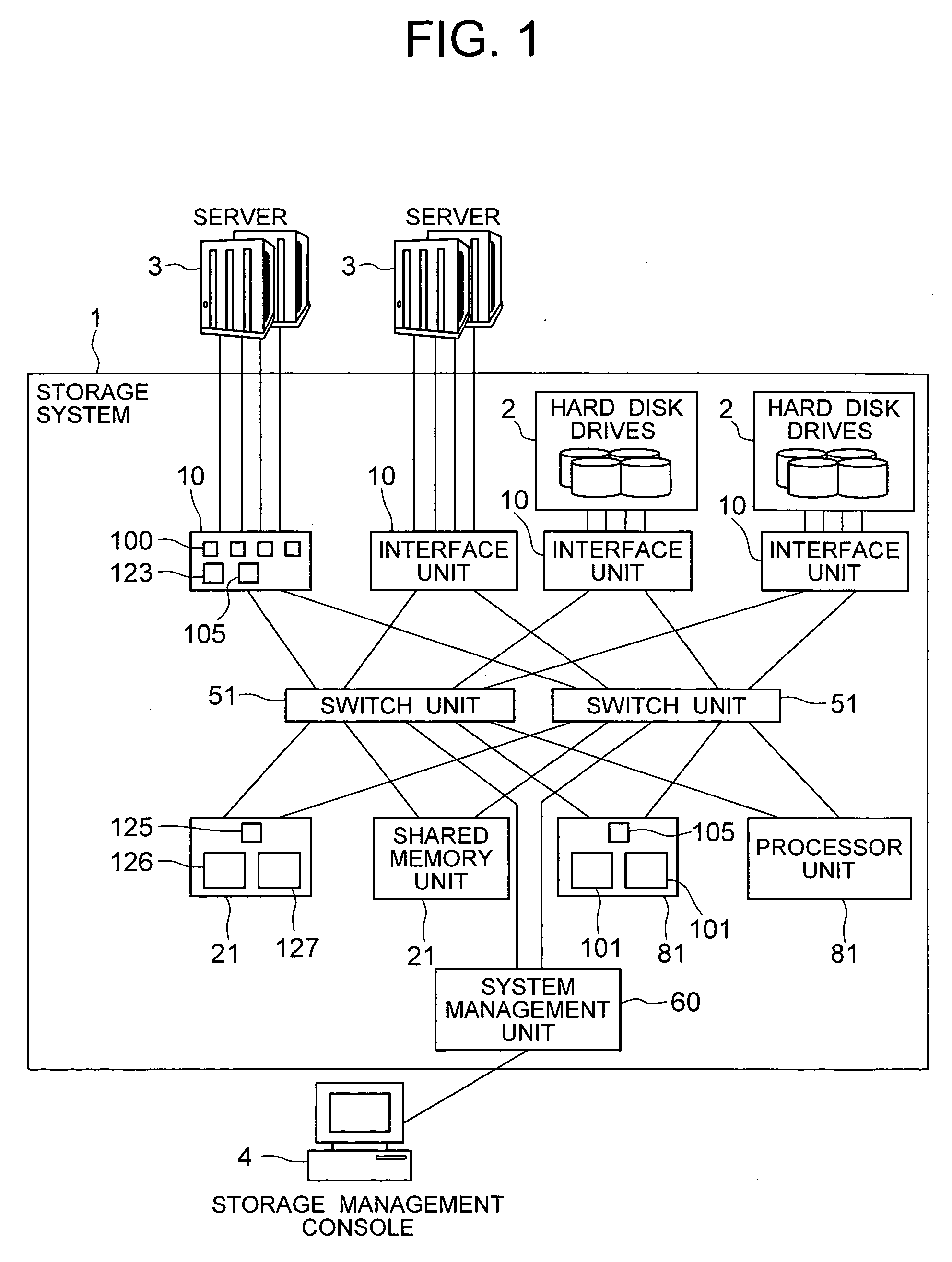
[0010] In view of the problems experienced in the conventional storage systems, it is an object of the present invention to provide a computer system which is capable of flexibly supporting user's requests to efficiently utilize resources of the computer system through simple configuration operations. Specifically, it is an object of the present invention to provide a storage system which is capable of allowing the user to set, through simple operations, an optimal correspondence relationship between interfaces (ports) connected to servers and hard disk drives accessed by processors and servers which process commands received through the interfaces associated therewith.
[0015] In particular, the storage system of the present invention can flexibly change an interface (port) for receiving commands from a computer, and a processor assigned to a data input / output process for the interface. Also, according to the present invention, the storage system can be configured in accordance with required performance with a computer connected thereto. It is therefore possible, according to the present invention, to efficiently utilize resources provided by the storage system.

Problems solved by technology

As a storage system becomes more important in a computer system, the storage system presents a challenge in a reduction of cost, including the operation and administration.
If the required performance for a server is not consistent with the performance of a processor assigned to handle input / output commands received from the server, the following problems can arise.
Specifically, when a processor has processing performance higher than predetermined required performance called for by a server which is connected to a port associated with the processor, the processor provides excessive processing performance.
On the other hand, when a processor has processing performance lower than predetermined required performance called for by a server which is connected to a port associated with the processor, the processor may fail to provide sufficient processing performance.
With this fixed correspondence, in the storage system of U.S. Pat. No. 6,385,681 B1, excessive processing performance can be provided by a processor associated with a port which is connected to a server that calls for low required performance, or insufficient processing performance can be provided by a processor associated with a port which is connected to a server that calls for high required performance.
However, U.S. Pat. No. 6,542,961 B1 does not particularly take into consideration how processors can be configured to effectively utilize resources provided by the system in accordance with required performance of the respective servers.

Method used


Image

  • Storage system, computer system, and method of configuring storage system
  • Storage system, computer system, and method of configuring storage system
  • Storage system, computer system, and method of configuring storage system

Examples


first embodiment

[0044] To begin with, a first embodiment of the present invention will be described.

[0045]FIG. 1 is a block diagram illustrating the configuration of a computer system according to the first embodiment of the present invention.

[0046] As illustrated, the computer system comprises a storage system 1; at least one server computer (hereinafter simply called the “server”) 3; and a storage management console 4. The storage system 1 and server 3 are interconnected, for example, through an interface called “Fibre Channel,” and communicate commands and data with each other using a protocol called “FCP” (Fibre Channel Protocol). The storage system 1 and storage management console 4 are interconnected through a LAN (Local Area Network).

[0047] In this embodiment, no particular limitations are imposed on the type of interface and protocol which are used between the storage system 1 and server 3. For example, a different combination of interface and protocol, such as Ethernet (registered trade...

second embodiment

[0158] Next, a second embodiment of the present invention will be described below.

[0159]FIG. 14 is a block diagram illustrating the configuration of a computer system according to the second embodiment of the present invention. The computer system according to the second embodiment differs in the configuration of the storage system from the computer system according to the first embodiment. In the description of the second embodiment, the same components as those in the first embodiment are designated the same reference numerals.

[0160] As illustrated, the storage system 1b in the second embodiment comprises two clusters 70a, 70b, each of which excludes the system management unit 60 from the storage system 1 in the first embodiment; and a system management unit 60 connected to a switch unit 51 included in each of the clusters 70a, 70b. Then, the switch unit 51 included in the cluster 70a is connected to the switch unit 51 included in the cluster 70b through an inter-cluster path.

[...

third embodiment

[0184] Next, a third embodiment of the present invention will be described below.

[0185]FIG. 17 is a block diagram illustrating the configuration of a computer system according to the third embodiment of the present invention. In the description of the third embodiment, the same components as those in the first embodiment are designated the same reference numerals.

[0186] As illustrated, the computer system comprises a storage system 1c, at least one server 3, and a storage management console 4. Similar to the first and second embodiments, in the computer system according to the third embodiment, the server 3 and storage management console 4 are connected to the storage system 1c. The computer system according to the third embodiment is identical to that of the first embodiment except for some differences in the configuration of the storage system 1c and the processes performed by the storage management console 4. Therefore, the following description will be centered on such differe...


PUM


Abstract

A storage system is provided with a plurality of interface units each for connection with a server; an interface unit for connection with hard disk drives; a plurality of microprocessor units each for processing commands; and a switch unit for interconnecting the interface units and microprocessor units. A management console is also connected to the storage system. The storage system forces the management console to select an unused interface unit from among the plurality of interface units for use in a data input / output process between the server and the storage system, select a microprocessor unit which meets required performance of the server from among the plurality of microprocessor units for use in the data input / output process, and notify the administrator of the selected interface unit and microprocessor unit.

Description

INCORPORATION BY REFERENCE [0001] The present application claims priority from Japanese application JP2004-137253 filed on May 6, 2004, the content of which is hereby incorporated by reference into this application. BACKGROUND OF THE INVENTION [0002] The present invention relates to a computer system, a storage system, and techniques for facilitating the configuration of the storage system on a management console. [0003] With the advance of information technologies, proliferation of the Internet, and the like, the amount of data handled by computer systems operated in enterprises continues to increase. Therefore, a storage system for preserving a large capacity of data is an essential material for a computer system. There are a variety of storage systems which provide a small scale to a large scale of configurations. [0004] As a storage system becomes more important in a computer system, the storage system presents a challenge in a reduction of cost, including the operation and admi...

Claims


Application Information

Patent Timeline
Patent Type & Authority Applications(United States)
IPC IPC(8): G06F15/16G06F3/06
CPCG06F3/0605G06F3/061G06F3/0683G06F3/0635G06F3/0629
Inventor SHIMOZONO, NORIOFUJIMOTO, KAZUHISAHONDA, KIYOSHIIWAMI, NAOKO
Owner GOOGLE LLC
Learn More