
Capacitors including interacting separators and surfactants

a technology of separators and capacitors, applied in the field of capacitor cells, can solve the problems of inefficient capacitor performance, difficult maneuvering and maintaining position, and difficulty in preventing short-circuiting or short-circuit conditions of capacitors, and achieve the effect of enhancing wettability and absorption of separators and preventing internal electrical short-circuit conditions

Inactive Publication Date: 2006-02-09
MEDTRONIC INC
View PDF27 Cites 20 Cited by
  • Summary
  • Abstract
  • Description
  • Claims
  • Application Information

AI Technical Summary

Benefits of technology

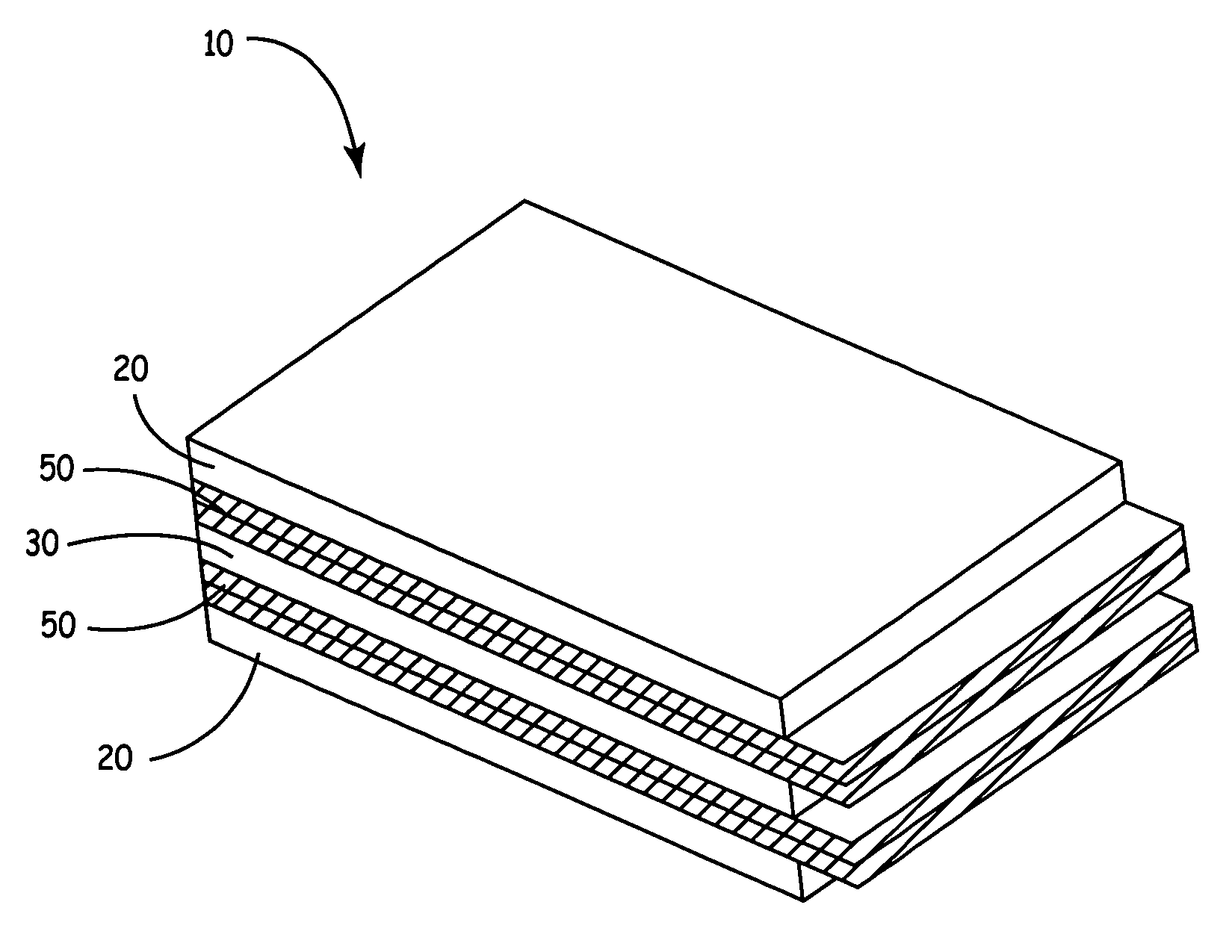
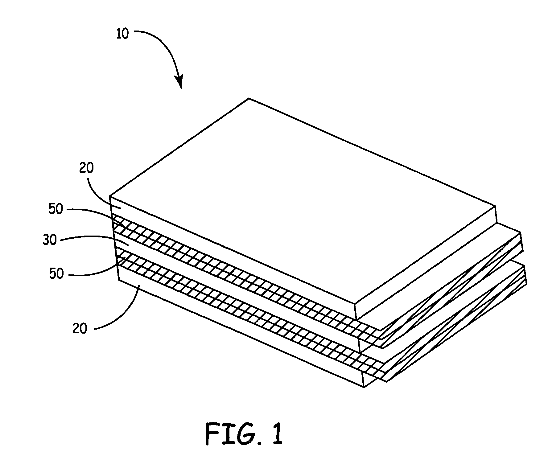
[0019] The present invention relates to capacitor cells and the utilization of separator materials that interact with one or more surfactants in such cells. In various embodiments, the capacitor cell of the present invention comprises one or more anodes, one or more cathodes operatively associated with the anodes, an electrolyte operatively associated with the anodes and the cathodes, one or more separators provided in between the anodes and the cathodes to prevent internal electrical short circuit conditions and to allow sufficient movement of the electrolyte within the capacitor cell and one or more surfactants for enhancing the wettability and absorption of the separators.
[0021] Additionally, capacitor cells according to the present invention further include one or more surfactants for stimulating and enhancing the wettability and / or absorption of the separator material. In some embodiments of the present invention, the separators are impregnated with the one or more surfactants. It is noted that the impregnated separators may also be optionally crosslinked with a crosslinking reagent to thereby retain the surfactant within the separator material. Alternatively, the one or more surfactants may be mixed with the electrolyte and interact with the separators upon administering the electrolyte to the other components of the capacitor cell. Examples of surfactants utilized in the present invention include, but are not limited to polyvinyl alcohol, dextran, agarose, alginate, polyacrylamide, polyglycidol, polyvinyl alcohol-co-polyethylene, poly(vinyl acetate-co-vinyl alcohol), polyacrylic acid, polyamide, polypeptides, poly-lysine, polyethyleneimine, poly-.beta.-malic acid, hyaluronic acid, derivatives of hyaluronic acid, polysaccharides, polyvinylpyrrolidone, and combinations or copolymers thereof.
[0022] The present invention also provides methods of making a capacitor cell that includes separators that interact with surfactants. In one embodiment of the present invention the capacitor cell may be produced by first providing one or more separators, one or more anodes and one or more cathode. It is noted that the separators may be administered with one or more surfactants to enhance the wettability and absorption of the separators. As previously suggested the separators may be impregnated with the surfactants or exposed to the surfactants when contacted with an electrolyte. Once the separators, anodes (fully anodized in the case of powdered metal anodes) and cathodes are present, the separators are positioned between the anodes and cathodes so that the anodes and cathodes are unable to come in physical contact with each other. For flat electrolytic and cylindrical type capacitors the alternating anodes and cathodes that are separated by separator material, are inserted into a cell enclosure. An electrolyte is then placed into the cell enclosure to activate the anodes and cathodes. Finally, the enclosure is sealed to retain and maintain the separators, anodes, cathodes surfactants and electrolyte within the enclosure.

Problems solved by technology

Alignment of the anode and cathode plates in flat capacitor cells again can be somewhat problematic in that the plates are generally small and difficult to maneuver and maintain in position during assembly of the capacitor cell.
Failure to align these components may lead to short-circuiting or inefficient capacitor performance.
Build-up of static charge in the separator material during manufacture of such capacitors can make handling of the material particularly troublesome.
All of these techniques have the disadvantage or requiring extra machinery or capacitor components that would not otherwise be required.

Method used


Image

  • Capacitors including interacting separators and surfactants
  • Capacitors including interacting separators and surfactants
  • Capacitors including interacting separators and surfactants

Examples


Embodiment Construction

[0024] The present invention comprises a capacitor cell generally including one or more cathodes, one or more anodes, one or more separators disposed between each anode and cathode pair, an electrolyte and one or more surfactants, which enhance the wettability and absorption of the separator. More specifically, the capacitor cell of the present invention includes a separator that is impregnated with a surfactant or that absorbs and / or interacts with a surfactant to provide enhanced wettability and / or electrolyte absorption.

[0025] The separator utilized in the present invention may be produced from any suitable separator material including but not limited to 1) nonwoven polymers, such as polyesters, polystyrenes, aromatic polyesters, polycarbonates, polyolefins, including polyethylene, polyethylene terephthalate, polypropylene, vinyl plastics such as polyvinyl difluoride (PVDF), and cellulose esters such as cellulose nitrate, cellulose butyrate and cellulose acetate; 2) microporous ...


PUM

PropertyMeasurementUnit
thicknessaaaaaaaaaa
densityaaaaaaaaaa
thicknessaaaaaaaaaa

Abstract

The present invention relates generally to capacitor cells and the utilization of separator materials that interact with one or more surfactants in such cells. More specifically, the present invention is related to capacitor cells that include separators that are impregnated with a surfactant or that absorb and / or interact with a surfactant that is included in an electrolyte placed within the capacitor cell.

Description

CROSS REFERENCE TO RELATED APPLICATION [0001] This patent disclosure claims the benefit of prior provisional U.S. patent application Ser. No. 60 / 474,800 (Atty Dkt 539.2000.0), invented by Norton et al., filed 30 May 2003, and entitled, “Capacitor Cells Including Enhanced Separator Systems and Materials”—the contents of which are fully incorporated herein.FIELD OF THE INVENTION [0002] The present invention relates generally to capacitor cells and the utilization of separator materials that interact with one or more surfactants in such cells. More specifically, the present invention is related to capacitor cells that include separators that are impregnated with a surfactant or that absorb and / or interact with a surfactant that is included in an electrolyte placed within the cell. BACKGROUND OF THE INVENTION [0003] A capacitor cell typically comprises an anode having a dielectric layer, a separator, a cathode, and an electrolyte solution. The anode and cathode often comprise stacked or...

Claims


Application Information

Patent Timeline
Patent Type & Authority Applications(United States)
IPC IPC(8): H01G9/08H01G2/10H01G9/02H01G9/022
CPCH01G9/02Y10T29/417H01G9/022
Inventor NORTON, JOHN D.RORVICK, ANTHONY W.NIELSEN, CHRISTIAN S.
Owner MEDTRONIC INC
Learn More