Eureka AIR delivers breakthrough ideas for toughest innovation challenges, trusted by R&D personnel around the world.

Movable energy-saving communication machine room

A communication room, mobile technology, applied in the field of communication, can solve the problems of affecting the power generation efficiency of solar power generation panels, inconvenient movement, etc., and achieve the effect of reducing the risk of vibration damage, reducing vibration, and convenient use

Inactive Publication Date: 2019-02-19
合肥鸿坤通信工程有限公司
View PDF8 Cites 8 Cited by
  • Summary
  • Abstract
  • Description
  • Claims
  • Application Information

AI Technical Summary

Problems solved by technology

Most of the current communication equipment rooms are set up outdoors, and sometimes it is necessary to change the location. The traditional communication equipment room is a fixed structure, which is inconvenient when it needs to be moved; in addition, in order to reduce the power consumption of the communication equipment room, usually in the communication equipment room Solar panels are installed on the top of the solar panel, which can convert solar energy into electrical energy for use in the communication room, which is both energy-saving and environmentally friendly. It plays a role of shading, which in turn affects the power generation efficiency of solar panels

Method used


Image

  • Movable energy-saving communication machine room
  • Movable energy-saving communication machine room
  • Movable energy-saving communication machine room

Examples


Embodiment Construction

[0020] In order to make the purpose, technical solutions and advantages of the embodiments of the present invention clearer, the technical solutions in the embodiments of the present invention will be clearly and completely described below in conjunction with the drawings in the embodiments of the present invention. Obviously, the described embodiments It is a part of embodiments of the present invention, but not all embodiments. Based on the embodiments of the present invention, all other embodiments obtained by persons of ordinary skill in the art without creative efforts fall within the protection scope of the present invention.

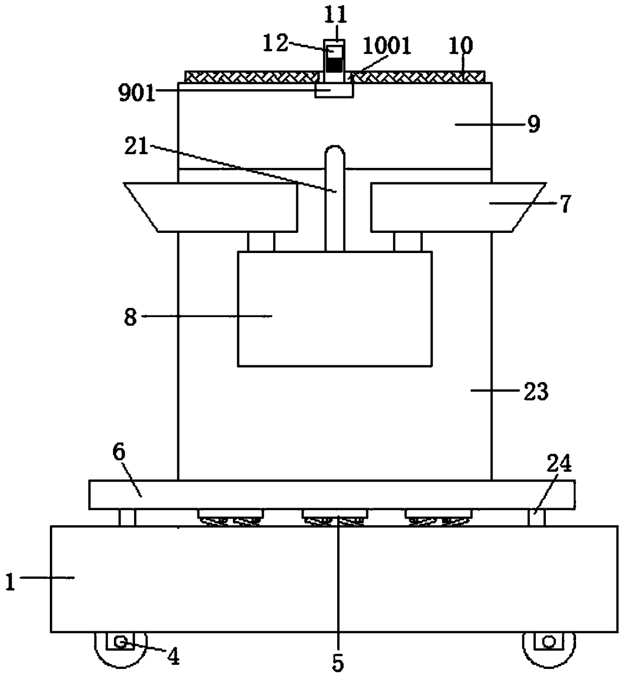
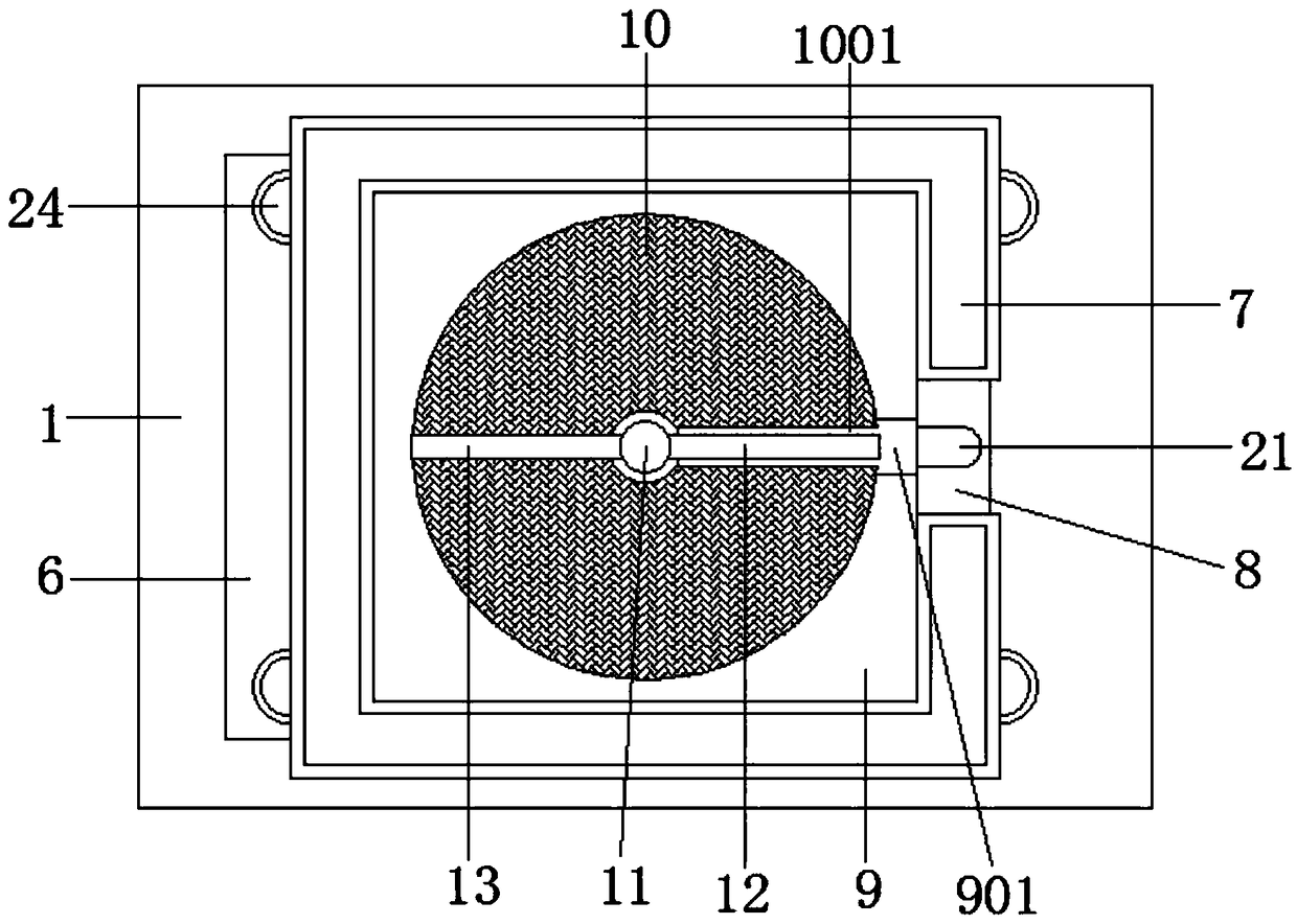
[0021] combine figure 2 , 3 , 4, see figure 1 : A mobile energy-saving communication machine room, comprising a base frame 1 and a communication machine room 23, characterized in that the left and right sides of the bottom of the base frame 1 are symmetrically provided with openings 101, and the left and right sides of the base frame 1 inner ca...


PUM


Abstract

The invention relates to the field of communication, in particular to a movable energy-saving communication machine room. The movable energy-saving communication machine room comprises a base frame and a communication machine room body; openings are symmetrically formed in the left and right sides of the bottom of the base frame; electric hydraulic telescopic rods are arranged on the left and right sides of the top of an inner cavity of the base frame correspondingly; a fixing plate is arranged at the bottoms of the electric hydraulic telescopic rods, and idler wheels are arranged on the leftand right sides of the bottom of the fixing plate correspondingly and penetrate through the openings; a groove is formed in the top of the base frame, and damping mechanisms are evenly arranged in thegroove; a supporting plate is arranged at the tops of the damping mechanisms; and limiting bolts are arranged at the four corners of the top of the supporting plate, and the lower ends of the limiting bolts penetrate through the supporting plate to be fixedly connected with the base frame. According to the movable energy-saving communication machine room, the design is novel, using is convenient,moving and fixing in the using process are facilitated, a solar power generation panel at the top of the machine room can further be automatically cleared, the photoelectric conversion efficiency ofthe solar power generation panel is improved, and the movable energy-saving communication machine room is suitable for being used and popularized.

Description

technical field [0001] The invention relates to the communication field, in particular to a mobile energy-saving communication machine room. Background technique [0002] Communication refers to the exchange and transmission of information between people or between people and nature through a certain behavior or medium. In a broad sense, it refers to the use of any method or medium by two or more parties who need information without violating their respective wishes. Accurate and secure transmission of information from one party to another. With the rapid development of science and technology, human beings have entered the era of network communication. [0003] The communication room is an important network communication equipment. Most of the current communication equipment rooms are set up outdoors, and sometimes it is necessary to change the location. The traditional communication equipment room is a fixed structure, which is inconvenient when it needs to be moved; in a...

Claims


Application Information

Patent Timeline
IPC IPC(8): E04H5/00E03B3/02E04B1/343E04B1/98H02S40/10
CPCE03B3/02E04B1/34336E04B1/34352E04B1/98E04H5/00H02S40/10Y02A20/108Y02E10/50
Inventor 李运茹
Owner 合肥鸿坤通信工程有限公司
Why Eureka
Eureka Blog
Learn More