
Waveguide diplexer of electric plane T-junction structure with resonant iris

a diplexer and electric plane technology, applied in the field of satellite waveguide structure, can solve the problems of affecting the performance of the filter, and the inability to raise the filter order according to the appropriate method, so as to prevent a transmission power, reduce the loss of insertion, and improve the filter performance

Inactive Publication Date: 2006-02-09
ELECTRONICS & TELECOMM RES INST
View PDF7 Cites 13 Cited by
  • Summary
  • Abstract
  • Description
  • Claims
  • Application Information

AI Technical Summary

Benefits of technology

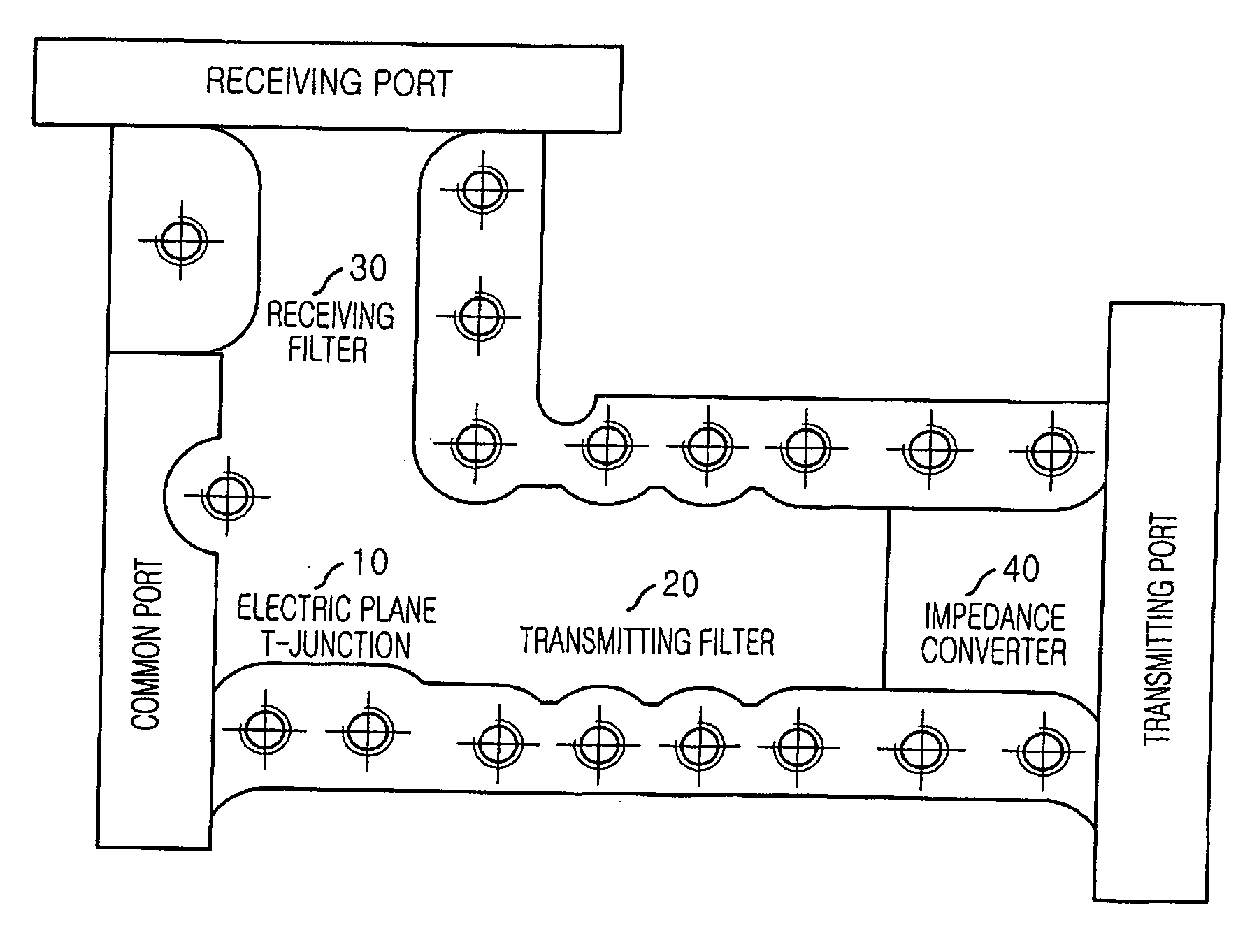
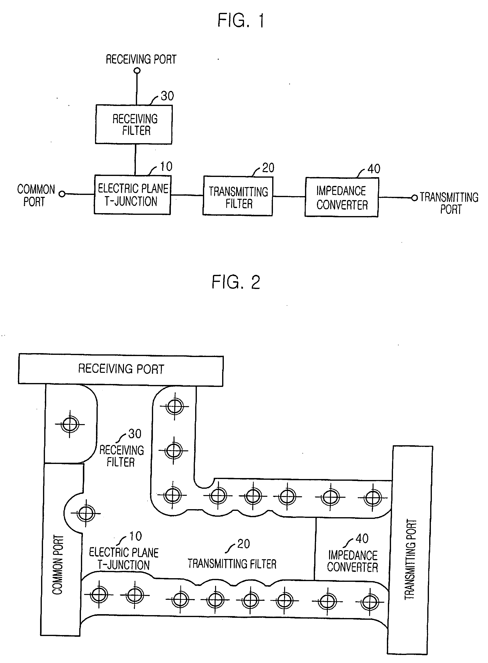
The present invention provides a waveguide diplexer with an electric plane T-junction structure that has a resonant iris for transferring a signal in high electric power through a transmitting path, transferring a signal with low insertion loss through a receiving path, and preventing a transmitting power to interfere to a receiver. The diplexer includes a transmitting filter, a receiving filter, an electric plane T-junction, and an impedance converter. The electric plane T-junction provides good isolation characteristics between a transmitter and a receiver. The diplexer has high isolation characteristics and can handle high power. The performance of the electric plane T-junction is increased by using the matching element (resonant iris).

Problems solved by technology

However, increase of filter's order may cause a breakdown when high power signal is passed through the filter because narrow gap of a waveguide in the filter.
By increasing the order of the filter, a gap of the waveguide in the filter becomes narrower and when the high power signal is passed through the narrow gap of the waveguide, the breakdown may be caused.
Therefore, raising the order of filter is not appropriate method for improving the performance of the filter.

Method used


Image

  • Waveguide diplexer of electric plane T-junction structure with resonant iris
  • Waveguide diplexer of electric plane T-junction structure with resonant iris
  • Waveguide diplexer of electric plane T-junction structure with resonant iris

Examples


Embodiment Construction

[0028] Reference will now be made in detail to the preferred embodiments of the present invention, examples of which are illustrated in the accompanying drawings.

[0029] Hereinafter, a fundamental principle of the present invention is explained.

[0030] In case of using a dominant mode of a rectangular waveguide, electric current is minimized at a center of broad wall of the rectangular waveguide. Therefore, a degradation of performance may be minimized when the center of broad wall is cut comparing other cross sections. Accordingly, a T-junction is better to be the electric plane structure than a magnetic plane structure for providing superior electric characteristic.

[0031] Also, a transmitting diplexer for a satellite must be designed for having sufficient multipaction margin in order to prevent a breakdown and be operated in a high electric power. A receiving diplexer must to be designed for minimizing loss in a passband for improving a noise characteristic of the satellite syste...


PUM


Abstract

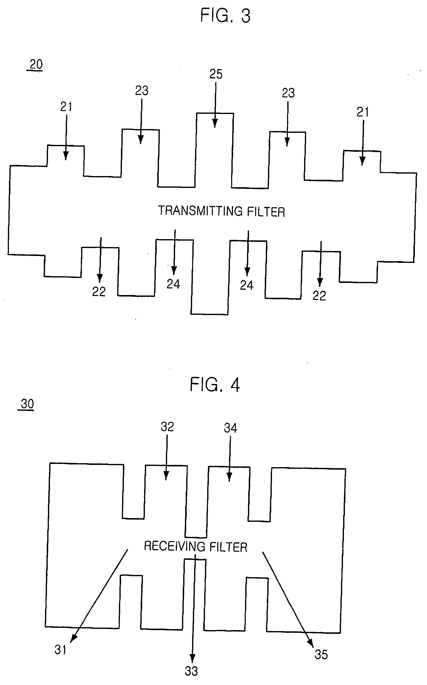
A waveguide diplexer having an electric plane T-junction structure with a resonant iris is disclosed. The waveguide includes: a waveguide having a predetermined shaped cross section; a transmitting filter for preventing to generate a harmonic band and a higher mode in a receiving band by changing impedance to have a low pass characteristic inside the waveguide; a receiving filter for minimizing an insertion loss by changing impedance to have a bandpass characteristic inside the waveguide; an electric plane T-junction for isolating / combining a transmitting signal and a receiving signal without electric interference by connecting the transmitting filter and the receiving filter, and minimizing interference of a frequency transmitted / received through the transmitting filter and the receiving filter; and an impedance converter for differentiating a transmitting port and a receiving port with minimum electric interference to the transmitting filter and the receiving filter by changing the impedance.

Description

FIELD OF THE INVENTION [0001] The present invention relates to a waveguide structure for a satellite; and, more particularly, to a waveguide diplexer having an electric plane junction structure with a resonant iris for transferring a signal in high electric power through a transmitting path, transferring a signal with low insertion loss through a receiving path, and preventing a transmitting power to interfere to a receiver by connecting a transmitting filter and a receiving filter with an electric plane junction providing good isolation characteristics between a transmitter and a receiver. DESCRIPTION OF THE PRIOR ART [0002] Generally, a waveguide diplexer is equipped at back of feeding horn in a satellite antenna feeder and isolates a transmitting signal and a receiving signal. For isolating, a waveguide diplexer having a T-junction form or a divider form is commonly used. [0003] The T-junction is classified to an electric plane junction and a magnetic plane junction. By using the...

Claims


Application Information

Patent Timeline
Patent Type & Authority Applications(United States)
IPC IPC(8): H01P1/213
CPCH01P1/2138H01P1/205
Inventor YUN, SO-HYEUNUHM, MAN-SEOKYOM, IN-BOKPARK, JONG-HEUNG
Owner ELECTRONICS & TELECOMM RES INST
Learn More