
Multi-frequency antenna and low-frequency radiation unit for restraining common-mode resonance

A radiating element and common-mode suppression technology, applied in the field of low-frequency radiating elements, can solve the problems of poor array system isolation, array system coupling interference, etc.

Active Publication Date: 2019-04-16
COMBA TELECOM TECH (GUANGZHOU) CO LTD
View PDF11 Cites 9 Cited by
  • Summary
  • Abstract
  • Description
  • Claims
  • Application Information

AI Technical Summary

Problems solved by technology

Multi-frequency antennas put forward more and more stringent requirements for miniaturization. The radiating units of different frequency bands need to be closely arranged to reduce the size of the multi-frequency antenna. Strong electromagnetic field coupling, especially the multi-frequency high-order mode of radiation unit coupling spurious in different frequency bands directly affects the normal operation of the original radiation unit working frequency band, which will cause strong coupling interference between different array systems, resulting in different arrays Poor isolation between systems

Method used


Image

  • Multi-frequency antenna and low-frequency radiation unit for restraining common-mode resonance
  • Multi-frequency antenna and low-frequency radiation unit for restraining common-mode resonance
  • Multi-frequency antenna and low-frequency radiation unit for restraining common-mode resonance

Examples


Embodiment Construction

[0037] In order to make the above objects, features and advantages of the present invention more comprehensible, specific implementations of the present invention will be described in detail below in conjunction with the accompanying drawings. In the following description, numerous specific details are set forth in order to provide a thorough understanding of the present invention. However, the present invention can be implemented in many other ways different from those described here, and those skilled in the art can make similar improvements without departing from the connotation of the present invention, so the present invention is not limited by the specific embodiments disclosed below.

[0038]In the description of the present invention, it should be understood that the terms "first" and "second" are used for description purposes only, and cannot be interpreted as indicating or implying relative importance or implicitly indicating the quantity of indicated technical featur...


PUM


Abstract

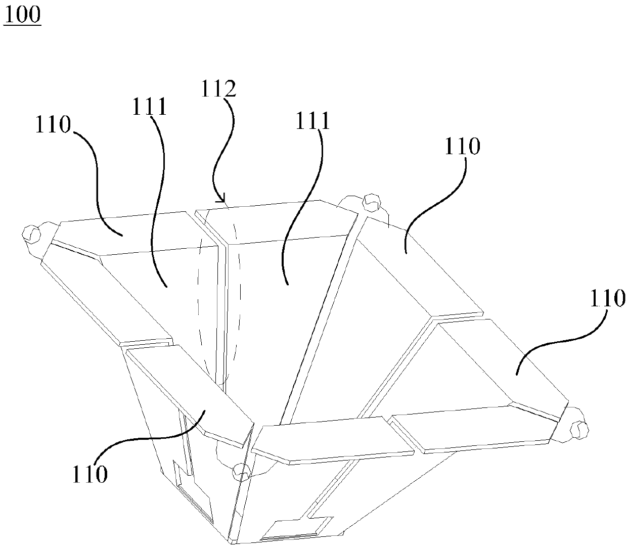
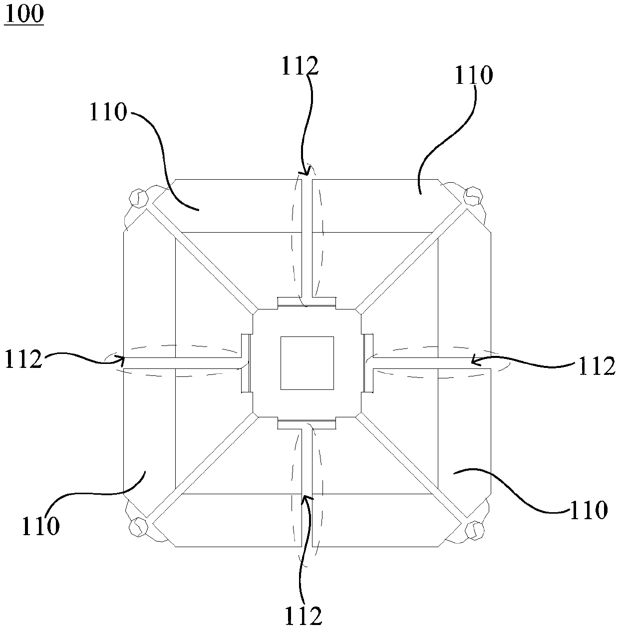
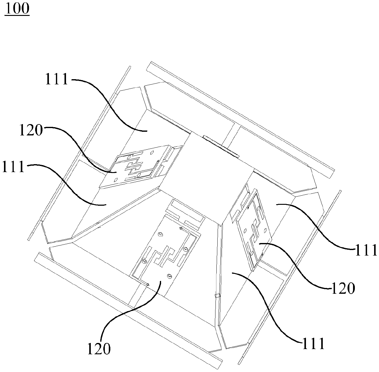
The invention relates to a multi-frequency antenna and a low-frequency radiation unit for restraining the common-mode resonance. The low-frequency radiation unit comprises a Balun fixing base, four half-wave oscillator structures and a restraining element. One side surface of the restraining element is a first metal surface, and the other side surface of the restraining element is a second metal surface. The first metal surface is respectively attached to two adjacent radiation arms respectively. The first metal surface and the radiation arms are in insulation fit with each other. The invention further discloses the low-frequency radiation unit for restraining the common-mode resonance. When the low-frequency radiation unit is arranged in the multi-frequency antenna, the adjacent radiationarms of the low-frequency radiation unit are directly equivalent to the full-metal sealing means for radio frequency signals in an ultra-wideband communication frequency band and a high-frequency communication frequency band. Therefore, a half-wave oscillator electromagnetic resonance structure of a high-order mode parasitic coupling resonance component on an oscillator of the low-frequency radiation unit is damaged in the physical structure. Thus, the common-mode resonance can be restrained. The coupling of the low-frequency signal electromagnetic energy of adjacent different polarized oscillation arms on the low-frequency radiation unit is reduced, and the polarization isolation degree of the low-frequency radiation unit is improved.

Description

technical field [0001] The invention relates to the technical field of antenna communication, in particular to a multi-frequency antenna and a low-frequency radiation unit for suppressing common-mode resonance. Background technique [0002] With the increase of mobile communication network standards, base station antennas are required to support multiple communication standards. In order to save site and antenna resources, multi-frequency antennas that can support multi-system communication have gradually become the first choice for operators to build networks. Multi-frequency antennas put forward more and more stringent requirements for miniaturization. The radiating units of different frequency bands need to be closely arranged to reduce the size of the multi-frequency antenna. Strong electromagnetic field coupling, especially the multi-frequency high-order mode of radiation unit coupling spurious in different frequency bands directly affects the normal operation of the or...

Claims


Application Information

Patent Timeline
IPC IPC(8): H01Q1/52H01Q1/36H01Q21/30H01Q19/10H01Q9/06
CPCH01Q1/36H01Q1/523H01Q9/06H01Q19/106H01Q21/30
Inventor 黎伟韶陈强陆国标
Owner COMBA TELECOM TECH (GUANGZHOU) CO LTD
Learn More