
Secondary battery

a secondary battery and battery body technology, applied in the field of secondary batteries, can solve the problems of fine gap between the plug, the electrolyte can leak through the gap, and the electrolyte can leak through the hole to the top of the electrolyte injection hole, so as to improve the safety of the secondary battery and prevent the electrolyte from leaking. , the effect of improving the sealing structur

Inactive Publication Date: 2006-02-02
SAMSUNG SDI CO LTD
View PDF3 Cites 43 Cited by
  • Summary
  • Abstract
  • Description
  • Claims
  • Application Information

AI Technical Summary

Benefits of technology

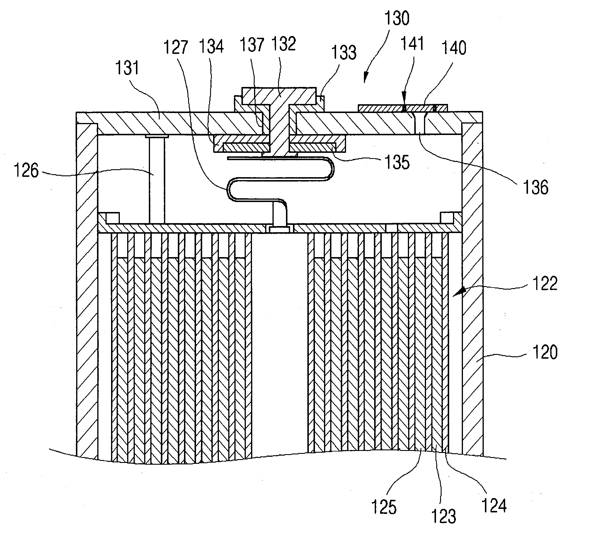
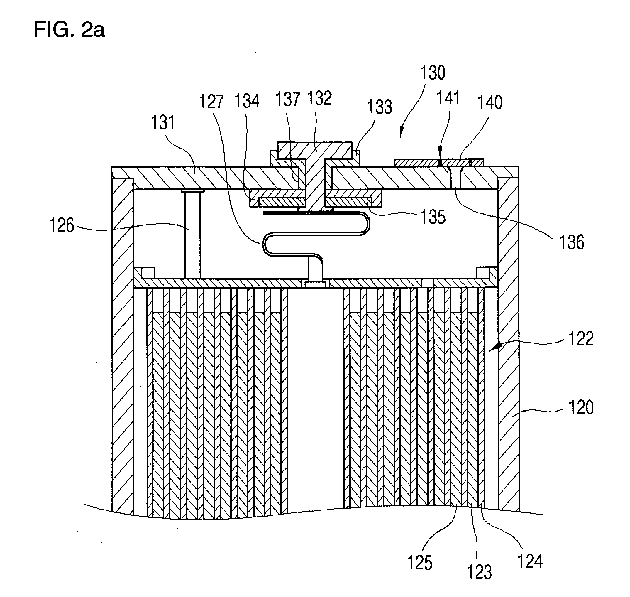
The present invention provides a secondary battery with an improved sealing structure to prevent electrolyte leakage and improve safety. The battery includes an electrode assembly, a can, a cap assembly, and a sealing plate. The sealing plate is welded to the cap assembly to seal the electrolyte injection hole. The sealing plate is made of a nickel metal plate and an upper aluminum metal plate bonded together. The sealing plate has a welded portion that surrounds the electrolyte injection hole and is at least two times the size of the hole. The sealing plate is welded to the cap assembly using a laser welding method. The secondary battery also includes a protective circuit module electrically coupled to the cap assembly. The technical effects of the invention include improved safety and prevention of electrolyte leakage.

Problems solved by technology

However, suchl secondary batteries have a problem in that, since the electrolyte injection hole is sealed by pressing a plug made of an aluminum ball therein, a fine gap tends to exist between the electrolyte injection hole and the plug and the electrolyte can leak through the gap.
Particularly, a larger amount of electrolyte is injected into the can, as secondary batteries tend to have larger capacity, and the electrolyte can leak to the top of the electrolyte injection hole due to the capillary phenomenon between the electrolyte injection hole and the pressed ball.
Consequently, the welding between the electrolyte injection hole and the ball becomes unstable due to the electrolyte and a pin hole is created at the welded portion.
As a result, a fine gap is formed between the electrolyte injection hole and the aluminum ball even when the aluminum ball is pressed into the electrolyte injection hole and the electrolyte can leak.

Method used


Image

  • Secondary battery
  • Secondary battery
  • Secondary battery

Examples


Embodiment Construction

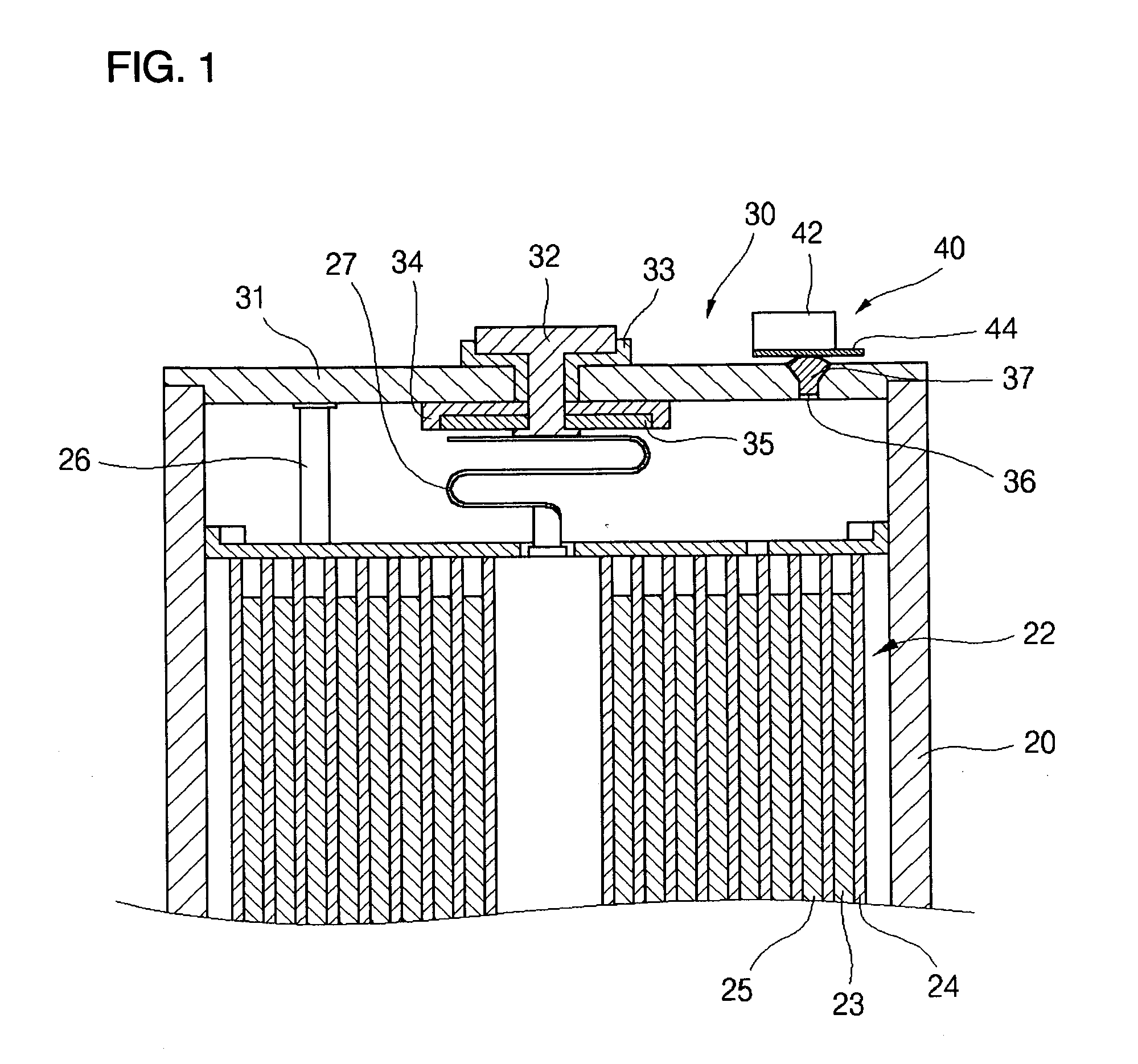
[0050]FIG. 1 is a partial sectional view of an upper portion of a secondary battery having an electrolyte injection hole formed on a cap plate of a bare cell.

[0051] Referring to FIG. 1, a can 20 is a metallic container having a cuboid shape with an open top and is preferably made of aluminum or an aluminum alloy which is light and conductive and which is resistant to corrosion. The can 20 acts as a container for an electrode assembly 22 including a positive electrode 23, a separator 24, and a negative electrode 25 and for an electrolyte. The electrode assembly 22 is inserted into the can 20 via an open top, i.e., the top opening, which is then sealed by a cap assembly 30.

[0052] The cap assembly 30 is provided with a planar cap plate 31 having a size and shape corresponding to that of the top opening of the can 20. The cap plate 31 is preferably made of the same material as the can 20 (i.e., aluminum or an aluminum alloy) for improved weldability to the can 20. The cap plate 31 has...


PUM

PropertyMeasurementUnit
depthaaaaaaaaaa
thicknessaaaaaaaaaa
thicknessaaaaaaaaaa

Abstract

In a secondary battery having an electrolyte injection hole having improved sealing structure to improve the safety of the can-type secondary battery and to prevent the electrolyte from leaking, the electrolyte injection hole is sealed by welding the sealing plate on top of the cap plate so that the electrolyte is prevented from flowing into the welded portion. Since no fine gap is created in the electrolyte injection hole, the electrolyte is prevented from flowing into the welded portion due to a capillary phenomenon and no pin hole caused by the electrolyte is formed in the welded portion.

Description

CLAIM OF PRIORITY [0001] This application makes reference to, incorporates the same herein, and claims all benefits accruing under 35 U.S.C. §119 from an application for SECONDARY BATTERY earlier filed in the Korean Intellectual Property Office on 25th of June 2004 and there duly assigned Serial No. 10-2004-0047999. BACKGROUND OF THE INVENTION [0002] 1. Field of the Invention [0003] The present invention relates to a secondary battery, and more particularly to a secondary battery having an electrolyte injection hole having an improved sealing structure to improve the safety of the secondary battery and to prevent the electrolyte from leaking. [0004] 2. Description of the Related Art [0005] As portable wireless appliances including video cameras, portable telephones, and portable computers tend to have reduced weight while incorporating more functions, much research has been conducted on secondary batteries which are used as the driving source of the appliances. For example, secondar...

Claims


Application Information

Patent Timeline
Patent Type & Authority Applications(United States)
IPC IPC(8): H01M2/08H01M2/36H01M2/26H01M50/184H01M50/186H01M50/191H01M50/193H01M50/197H01M50/198H01M50/574H01M50/636
CPCH01M2/08H01M2/34H01M6/10H01M2/365H01M2/361H01M50/636H01M50/184H01M50/186H01M50/193H01M50/198H01M50/574H01M50/191H01M50/197
Inventor YIM, HOONMAENG, SOO-YEONCHO, KYU-WOONG
Owner SAMSUNG SDI CO LTD
Learn More